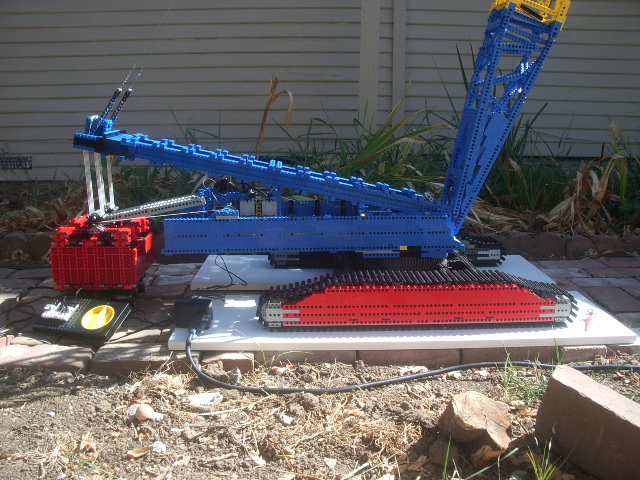
The following pictures show the largest crane I've built to date. This model took nearly one year to build and is still not finished. At this time (August 2004), it is fully functional but it still need some cosmetic touches, like an operator cab... This crane does not follow a particular prototype: it was inspired by similar machines from leihberr and Terex. I wanted a model that was easy to setup and take down so I could bring it to various BayLUG shows and actualy enjoy the show instead of spending the entire time setting up the crane!
To this effect, I built a simple crane with no boom extension. The main boom comes appart into two half. The A-frame folds down on the supper structure, keeping the the cable rigged. The supper structure is connected to the carrier base by three Technic cross axles. The boom is connected with two more cross axles. When I set it up to takethe pictures below, it took about 20 minutes from start to finish. Taking it appart takes about the same amount of time.
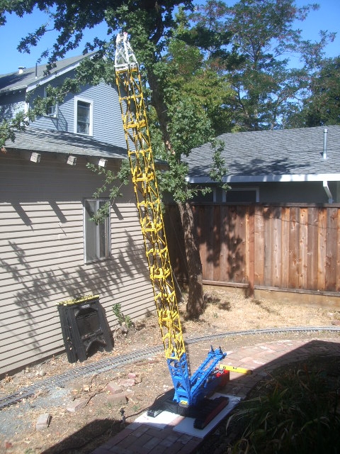
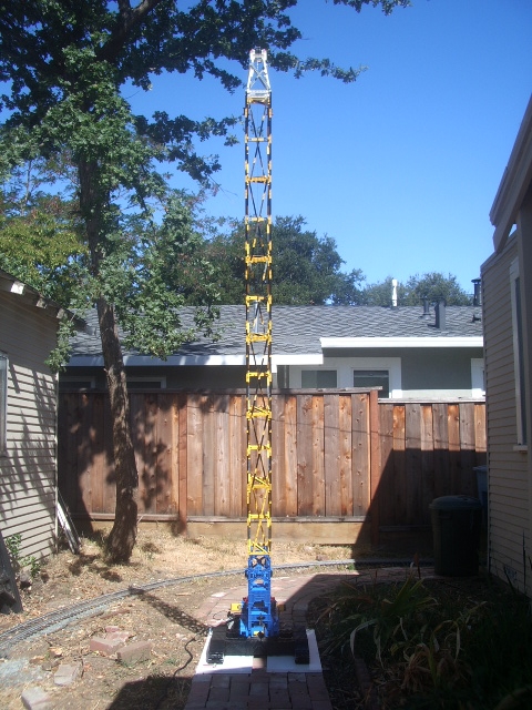
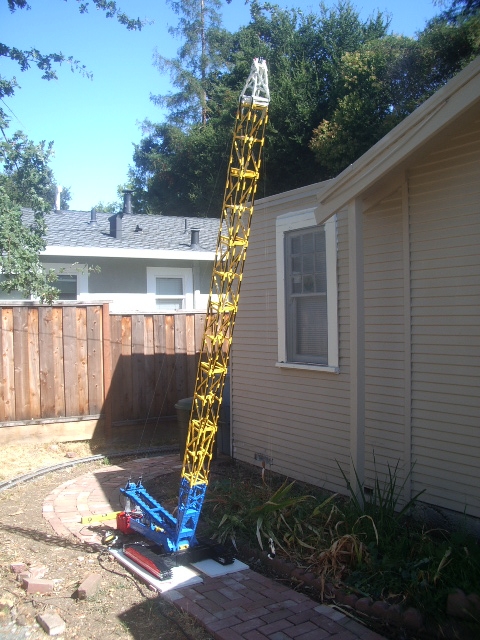
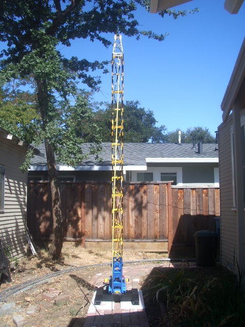
Here are some pictures of the first time I fully raised the boom (I had to take it outdoors because the ceiling in my house is too low).
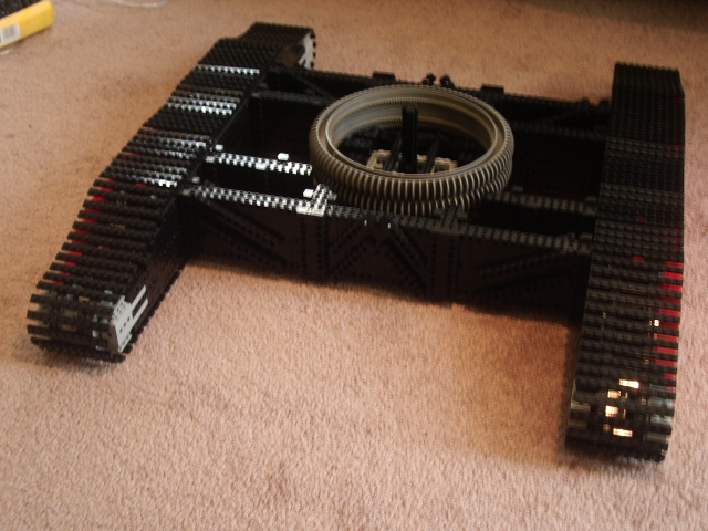
Here are a couple of views of the carrier and main body:
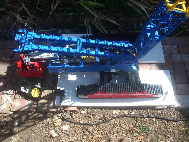
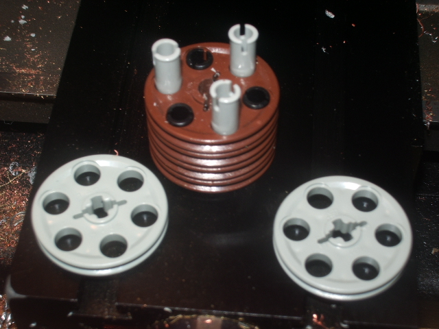
Here is a view of the counter weight. Most of weight is created by a stack of ferrite clamps designed for flat ribbon cables (ifyou don't know what this means, just think of a bunch of steel plates each wrapped in its own plastic housing). The remainder of the weight comes from about $10 worth of pennies...
The reason I placed the counter weight on its own chassis is to prevent excessive stress on the main body when there is no load on the boom. The chassis rides on four wheels which are steered up to 90 degrees, so the crane can either move in a straitline or slew while stopped. I'll add a picture of this mechanism soon...
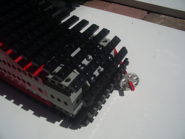
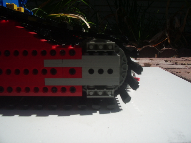
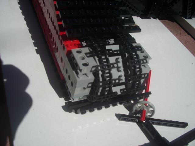
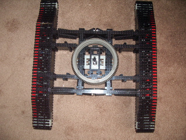
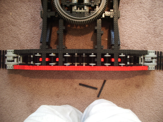
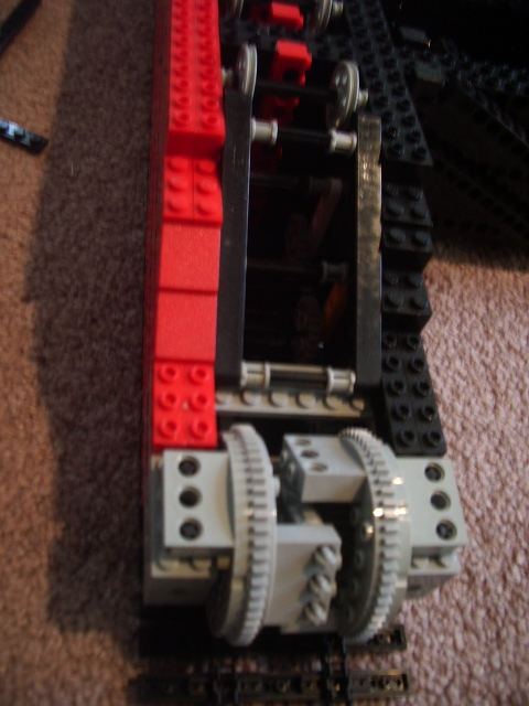
The crawlers are ten stud wide each. They are made of one by ten plates attached to two Tehcnic chains made of an alternance of narrow and wide links. The end gears are made of two Technic turn tables.
As soon as the boom was up, I realized I made a mistake in my design: due to the design of the boom's tip, the hook's cables touch the boom. Since these pictures were taken, I have rebuilt the tip to fix this problem. I will add some pictures soon... As a result of this problem, I decided not to try lifting any significant weight. I know it should be quite powerful, as an early test showed it can lift this truck with the boom at 45 degree!
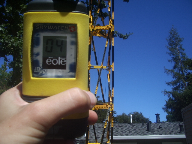
The next test will probably be indoors, because I don't want to lift any significant weight in the wind. The following picture shows a wind speed of 4MpH. I recorded as much as 10MpH gusts that day which resulted in the tip of the boom moving about half of its width on each side!
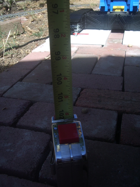
I did measure the height under the hook by lifting a tape measure. The following pictures show the setup. I measured 102 Inches plus 3 Inches for the tape measure's body plus about 6 inches for the rigging beteween the hook and the tip of the tape minus 2 inches for the wood plates onto which the crane is resting... So the total height under the hook is 109 Inches (2.76m). I don't expect it to change much with the new tip design, but I will measure it again...
September 2004: The crane is back home after spending a little over one week setup at my office. Both setup and take down went smoothly and aside from a couple of people accidently kicking the corner of one crawler, the crane sustained no damage. During its stay at the office it lifted one of my company's product, a 2.5Kg steering wheel used for video games, without problems. The boom made some creaking noises but it held well and all the parts stayed firmly in place. I don't think I'll ever try lifting more weight! While on the subject of weight: I checked the counter weight on precision scale, its mass is 6.5Kg.
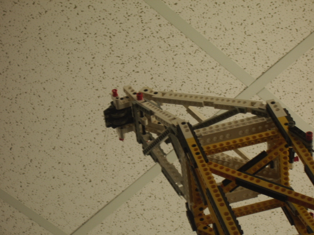
This also marked the first time the new tip was used and it turned out to be a complete success! Here is a view of it (using my camera's 3 time zoom to its fullest extend):
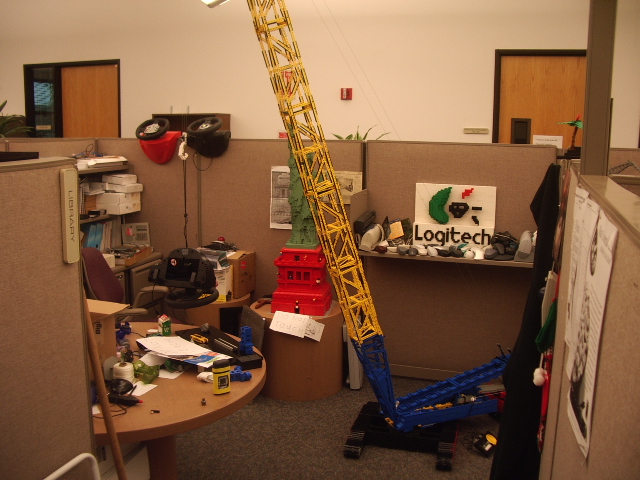
Here is an overall view of the crane while it was lifting a 2.5Kg steering wheel (Notice that is is suspended by its interface cable: don't try this at home kids!).
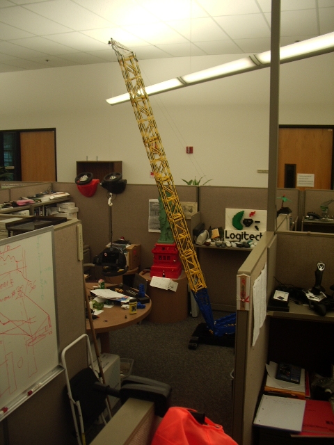
Both the Statue of Liberty and the big Logitech logo are permanent resisdent of the office. If you look in the bottom left corner of the picture, you'll see (among other things) a diagram on a white board: I drew this while explaining to one of my colleague how the crane was built, the day before I brought it in...
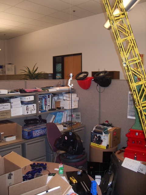
Here are a couple more pictures of the lift. Next time I lift something, I'll make sure the background is a little less busy.
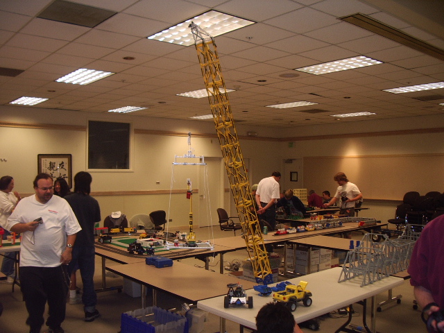
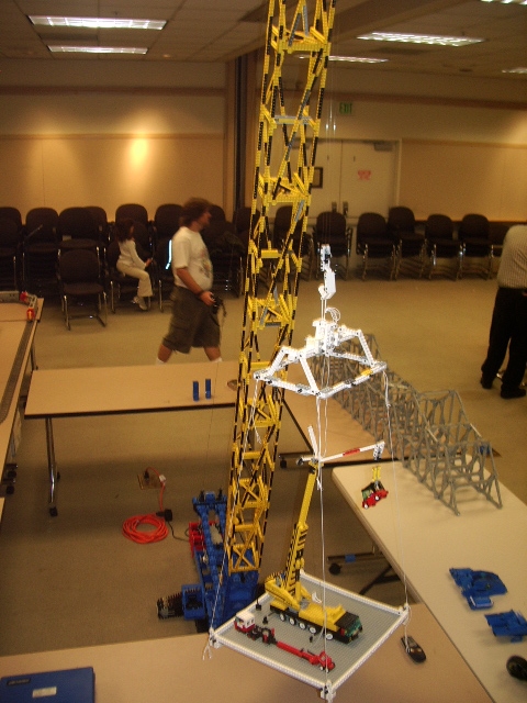
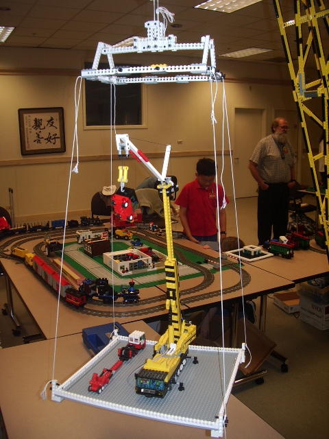
October 2004: I setup the crane in public for the first time as part of BayLUG's show at the Fremont library. The night before the show I decided to use my minifig-scale crane as a load. Instead of just lifting that crane in its road ready configuration, I decided to lift it while fully deployed. This meant designing, building and testing a rigid base and riging setup for it in only a couple of hours... The result is far from pretty, but it works!
At the show we normaly setup our models on tables, but I quickly realized that the ceiling would be too low for the crane, so I set it up on the floor and surounded it with tables to protect it ... The following pictures show the completed setup...
Construction details:
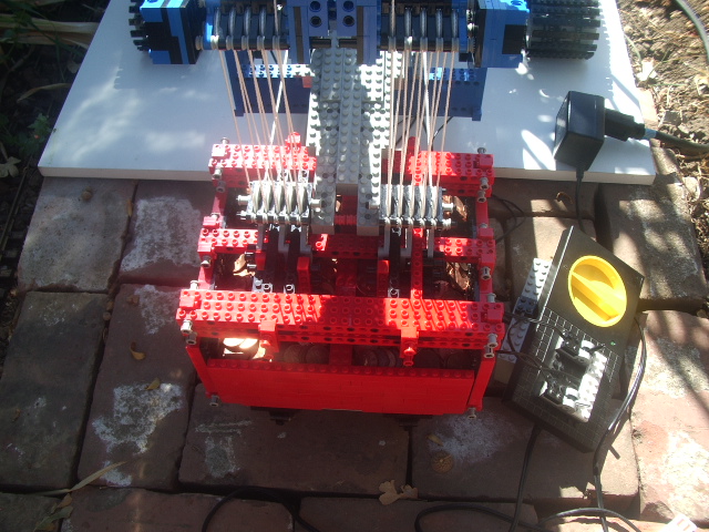
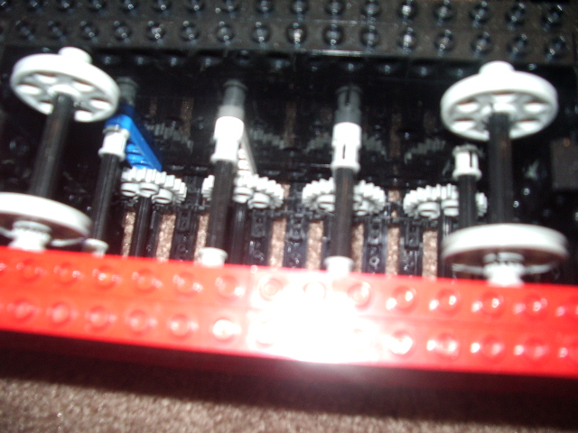
The boom is raised by pulling the A frame back down. In order to have both a reasonable speed and enough torque (during construction, a test with a force gauge showed it takes atleast 150N of force to get the boom off the ground), the winch uses four motors geared 1:5, followed by a nine part line. A test with a force gauge showed that the winch by itself can develop up to 30N of force (with the motors stalled), so in theory, the complete system can develop 270N of force.
The winch is split into two halves, each one connected to its own nine part line. This duplication of pulleys and lines is required to keep the A frame from twisting while moving. My previous large crane did not have this feature and left to its own design it would twist itself to the point of breaking the A frame appart... Since it is very hard to have two spools wind their cables in the exact same way, the system is equalized: instead of attaching the end of the two cables to the A frame, the system uses one cable with the two sides connected by pulleys. The following diagram illustrates this principle. I must point out that this is not an original design: I found it here, thanks Ross!
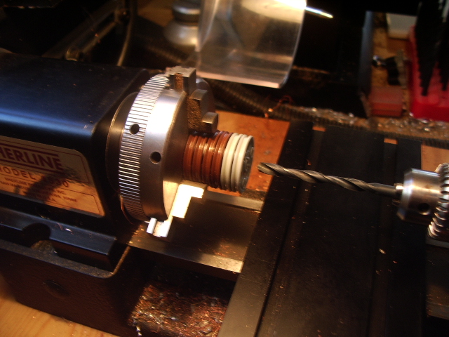
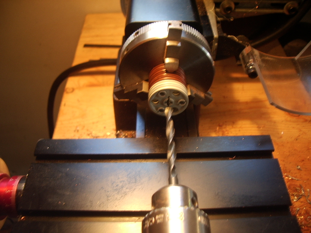
In order to have several pulleys on the same axle that can rotate independently from eachother, i had to drill out the cross axle shape out of the Lego pulleys. Normaly, I don't like modifing bricks: I like the challenges created by the limitations of the Lego geometry and part availability. In this case, though, the modification is so simple and the benefits are so great that I decided to make an exception. The following pictures show the setup on my lathe for drilling the parts. The four brown pulleys are "sacrificial" parts: the steel jaws of the lathe chuck damage their rims. The wheels are drilled two at a time; the whole process takes less time to do than it takes to explain it...
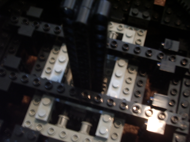
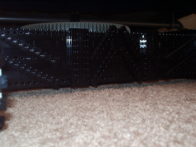
The crawler base and the main body are made mostly of technic beams separated by two layer of plates. In areas where I needed more height and had no need to use the pin holes in the beams, I used the following structure: one beam, one plate, two regular bricks and then the next beam. Once a section was complete I added some vertical and diagonal cross beams, creating a truss structure.Here are a few pictures of the crawler base by itself. It is built as one single unit, to keep it simple and robust.
The colors were dictated by the availability of bricks in my collection. Except for some extra chains and Technic turn tables, I did not buy any parts specifically for this project. I did aquire a friend's entire Technic collection though...
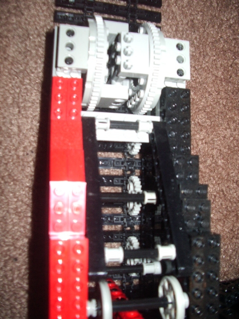
The main winch is based on a design from TJ Avery, as shown on his site. It features four motors driving a single spool through a 1:5 (8:40) gear ratio. This gives both plenty of torque and a good speed. The spool itself is based on the design used by Ross Crowford for his CC2800, but is a little different because I was not looking at the website at the time I built it... Now I wish I had taken a picture of it before I wound an entire spool of fishing line on it...
This page is Copyright 2004, David Wegmuller. For website feedback, send a message to webmaster at wegmuller dot org. For content feedback, send a message to david at wegmuller dot org. Lego and Lego Technic are trademarks of the Lego Group. This website is not related, sponsored or endorced by the Lego Group.