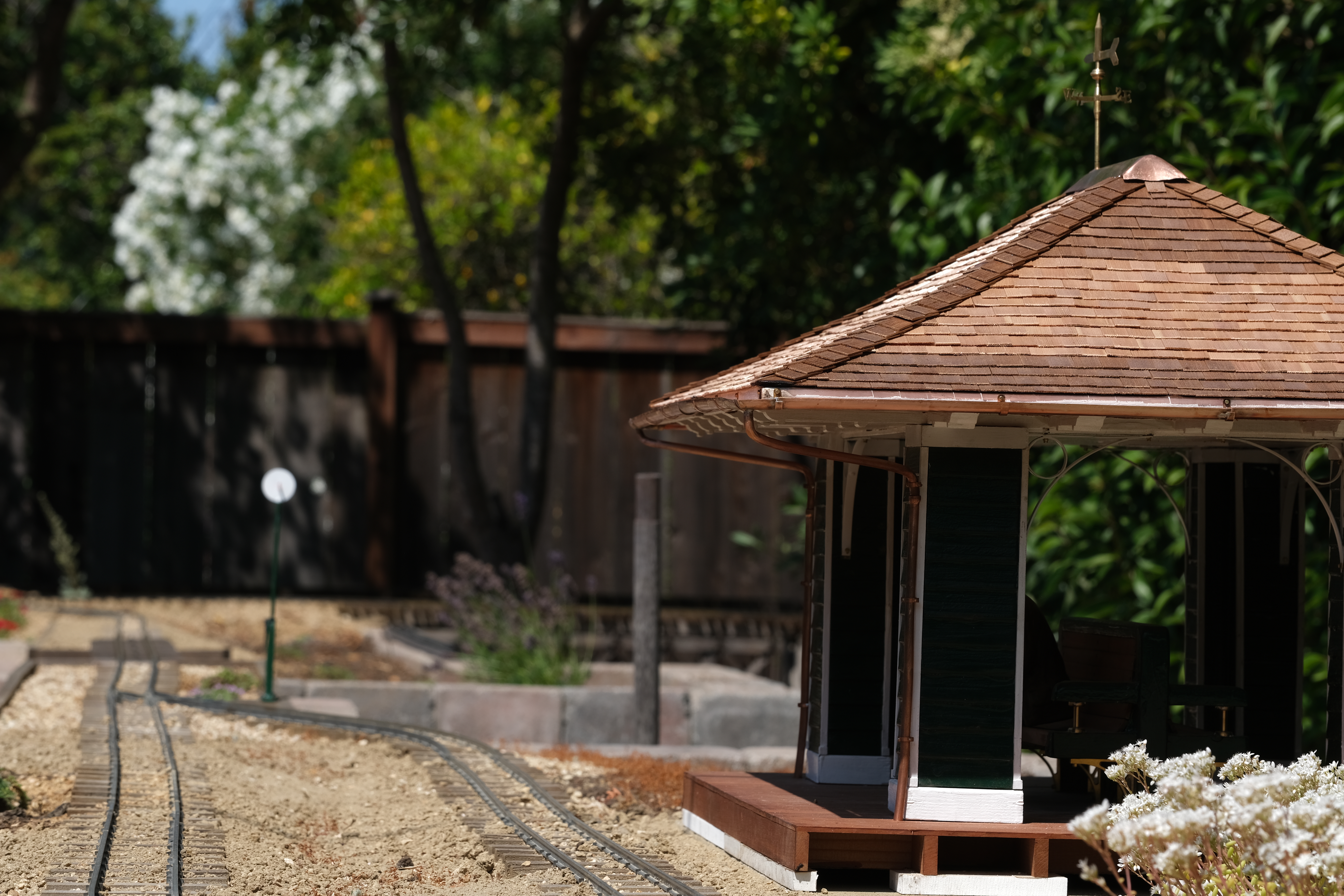
1:8 Scale Train Station
Building a train station based on an unbuilt SPC prototype.
Introduction
In the late 19th Century, the South Pacific Coast RR built a branch line from Newark to Centerville (now part of Fremont, CA). One of its stops was Arden. This model is based on the original plans for this station.
The only photos that survive show a much simpler structure with two posts. It is not clear if the station was built per original plans and then rebuilt or if the original plans were never built.
The plans were commisoned by Mrs Patterson and were found in the estate of George Patterson when his house and grounds (now Ardenwood farm in Fremont) were sold in the 1970's. My model is based on plans published in the book "Narrow Gauge Portrait South Pacific Coast" by Bruce A. MacGregor.
Construction
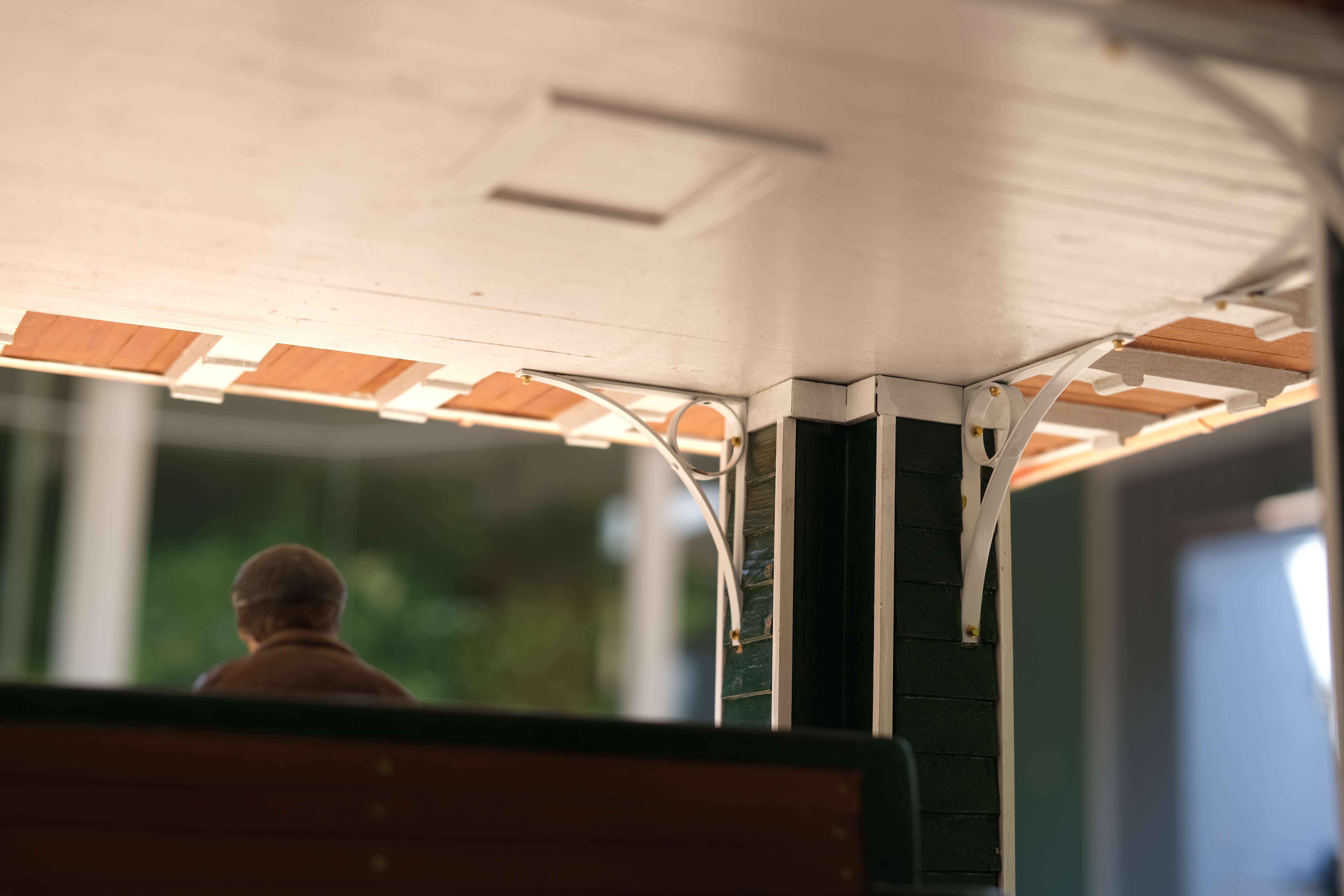
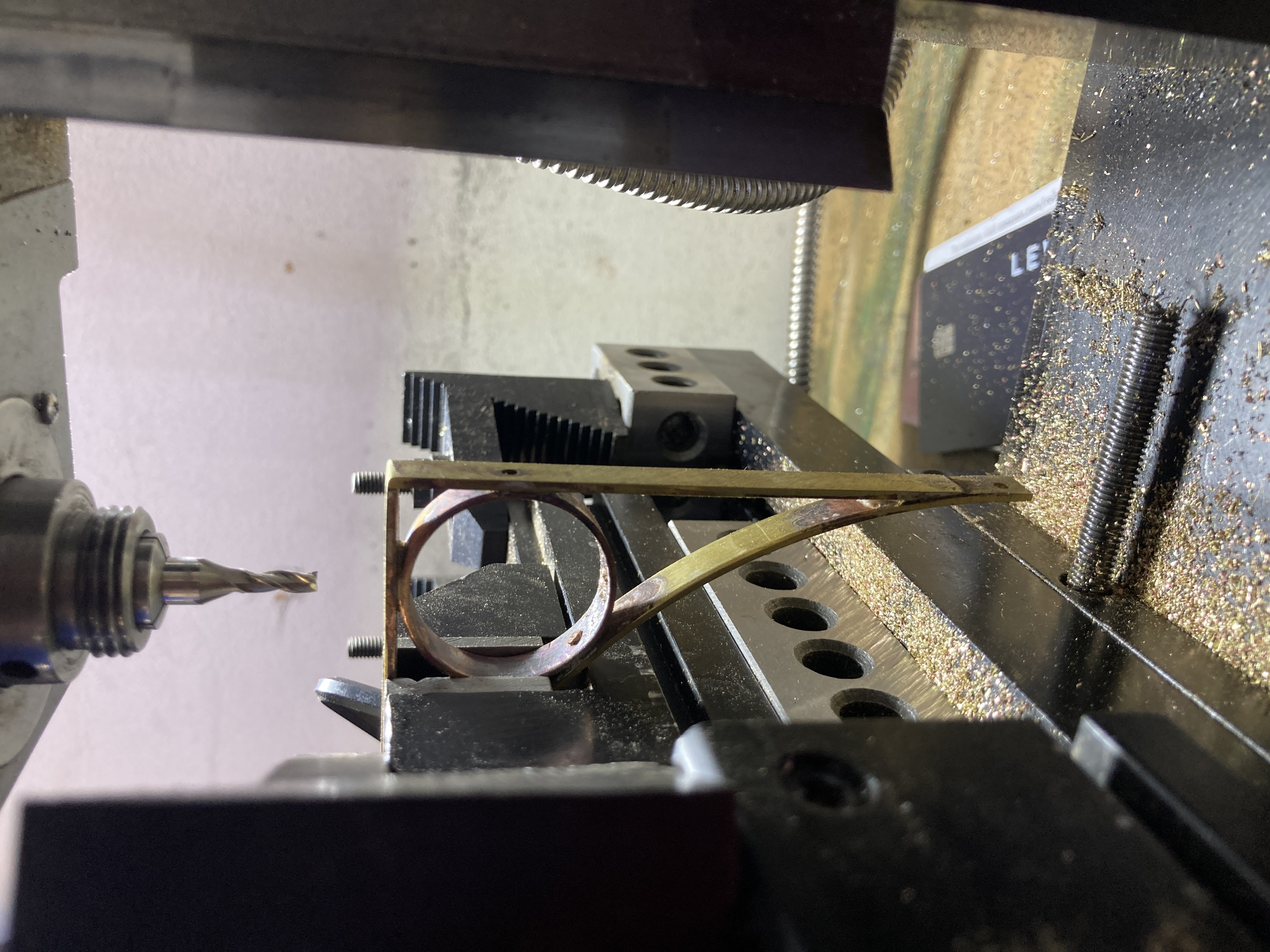
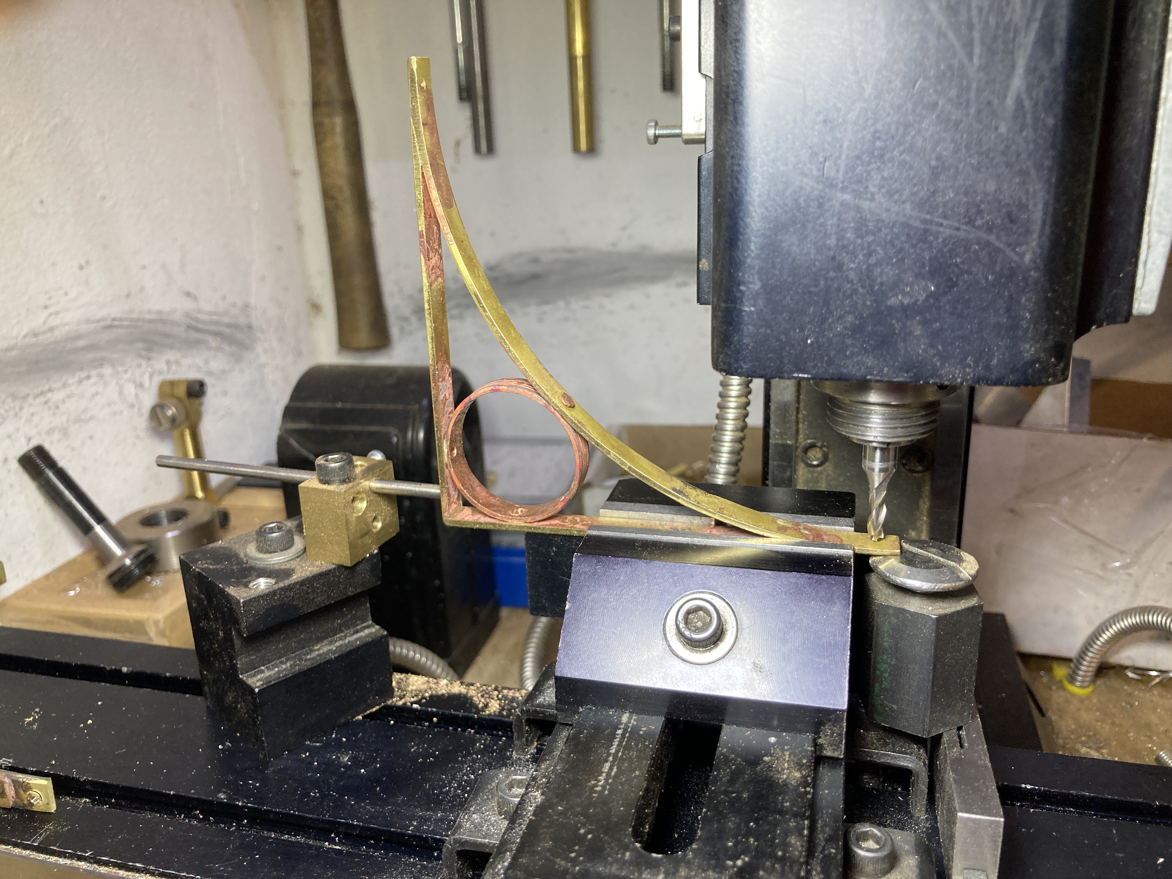
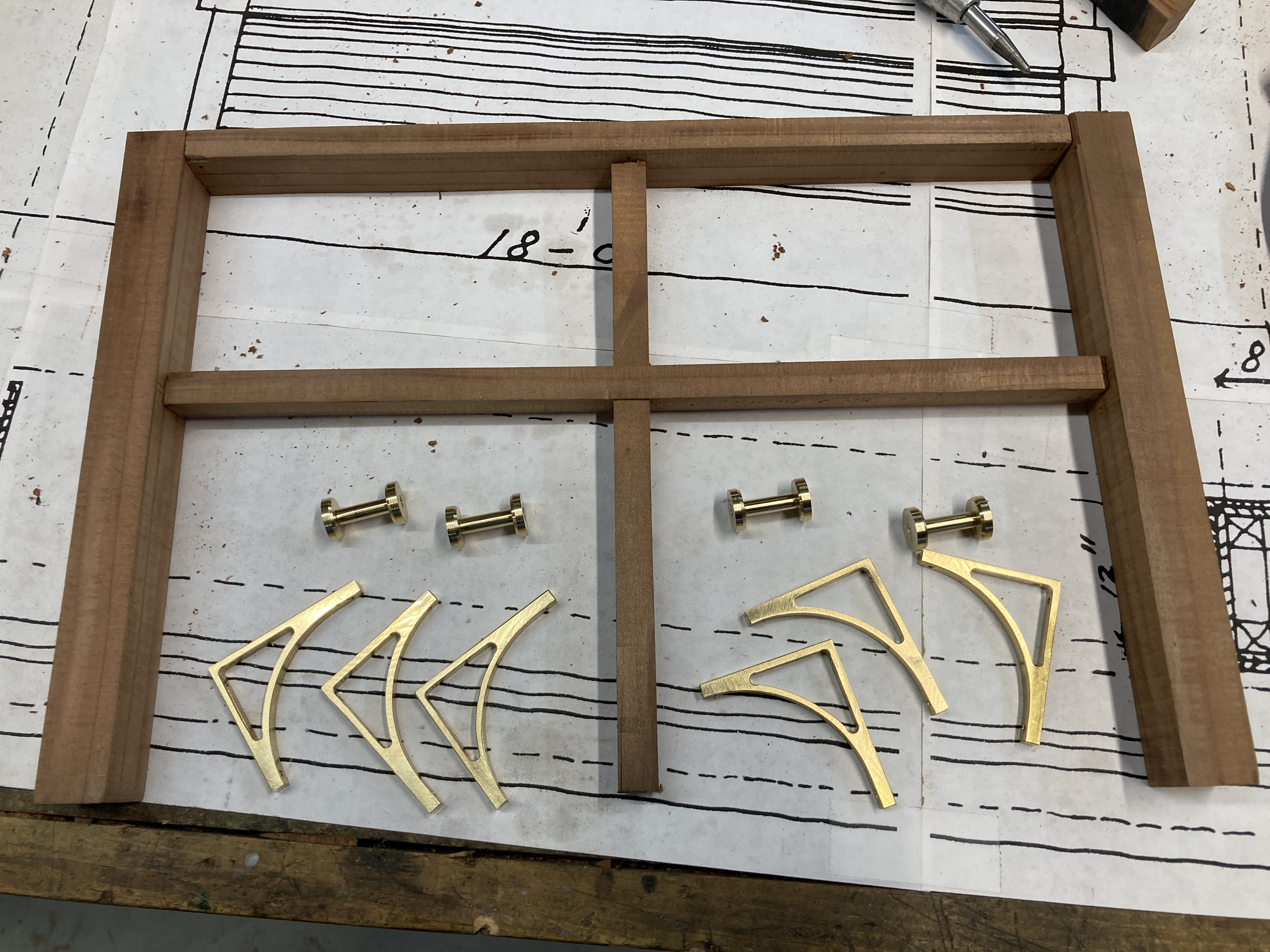
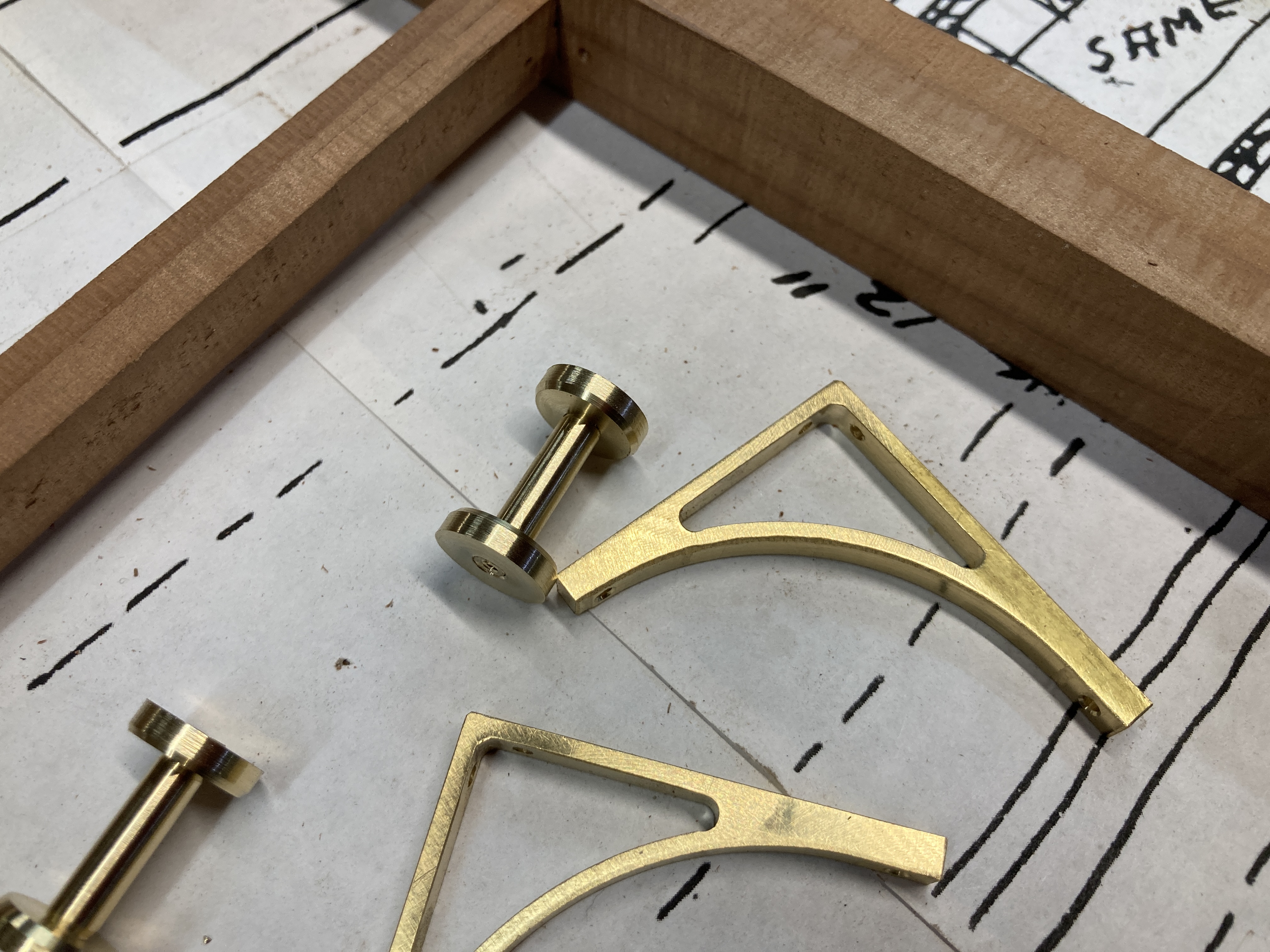
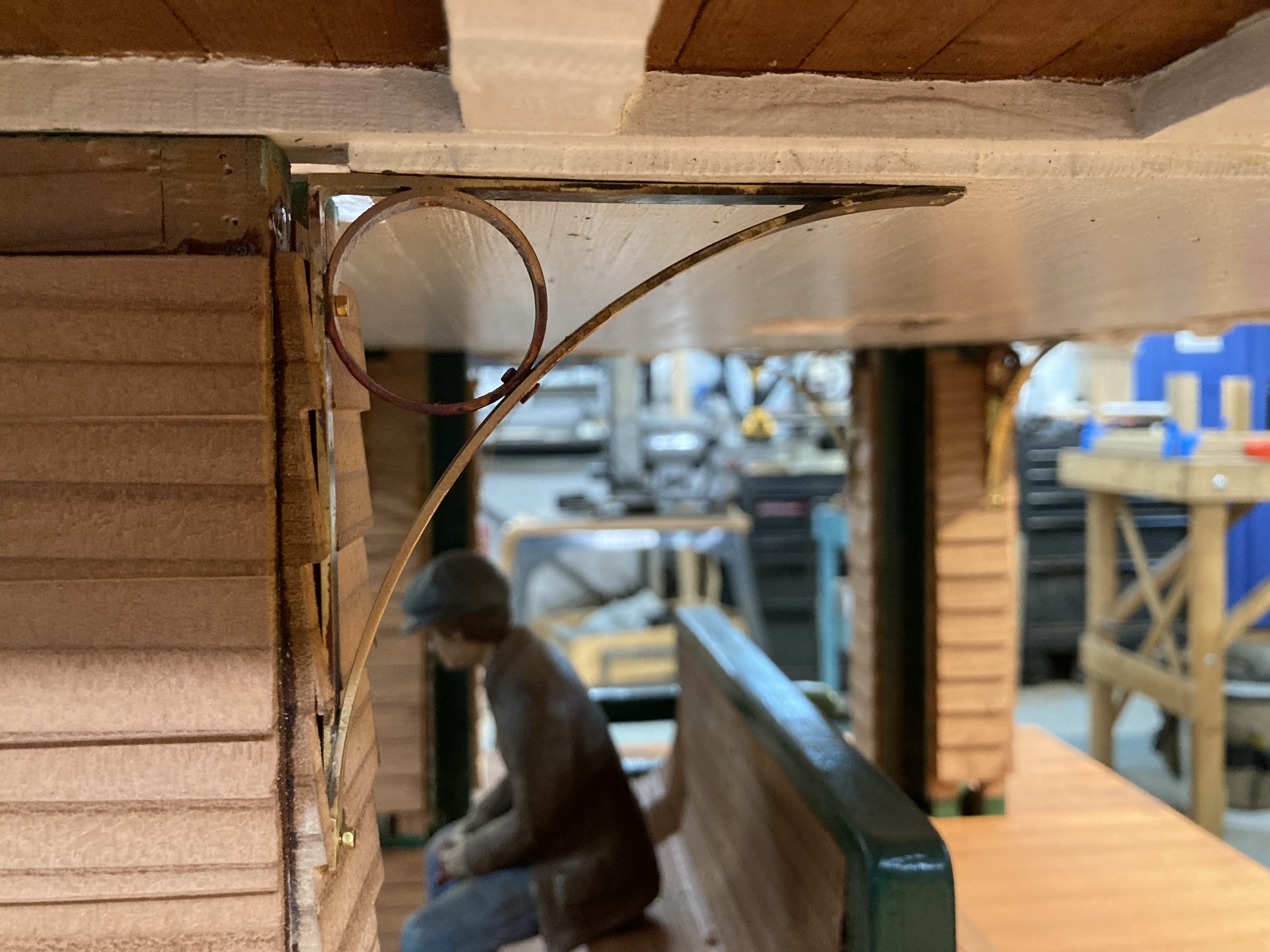
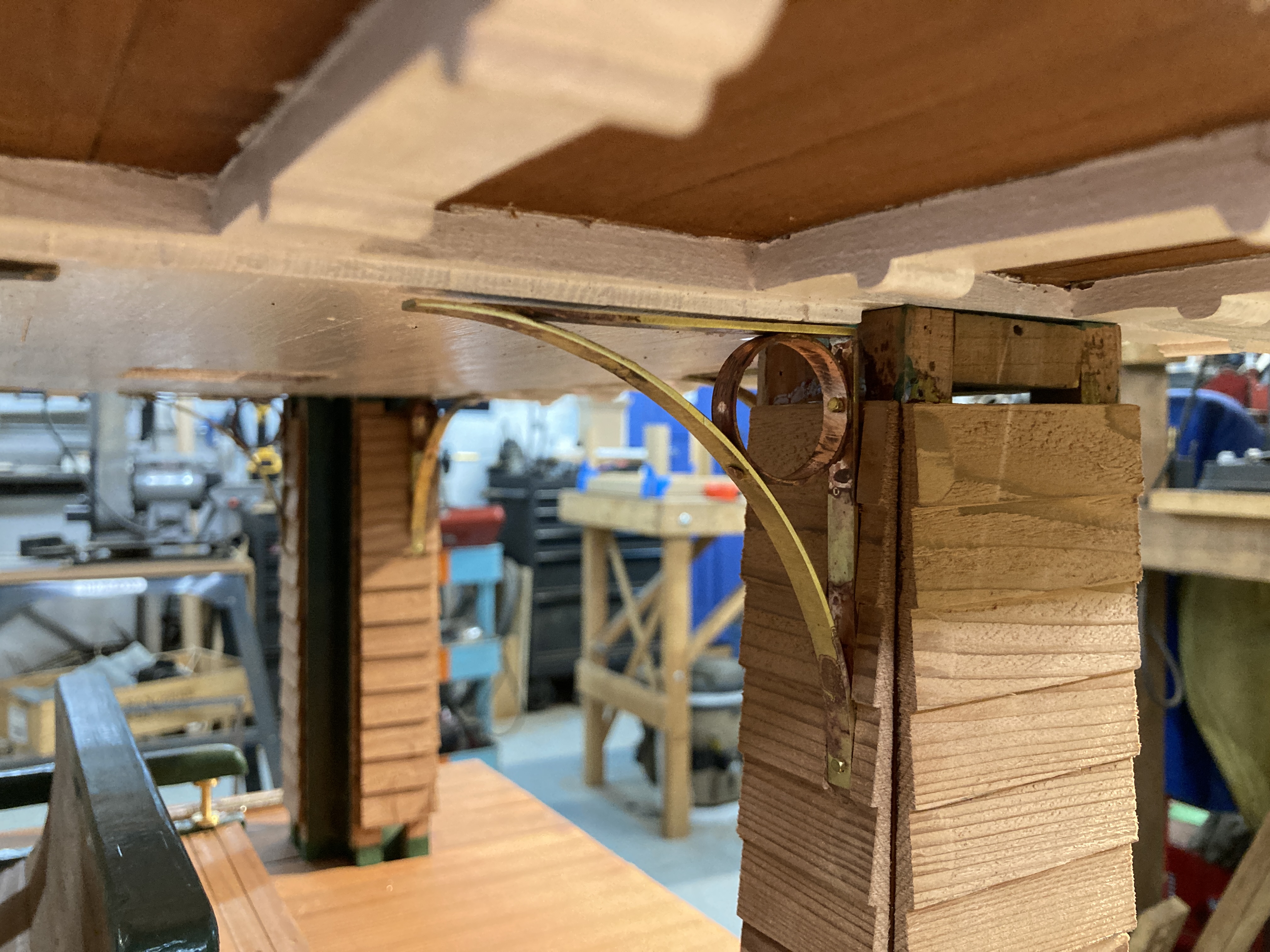
I started by making the brackets that connect the columns to the ceiling and roof structure. The original drwaing called for cast iron brackets: I made mine out of brass and copper
To make the curved segments, I roughly rolled two oversize loops made of flat stock which I then turned to size and split into four quarter circles each.
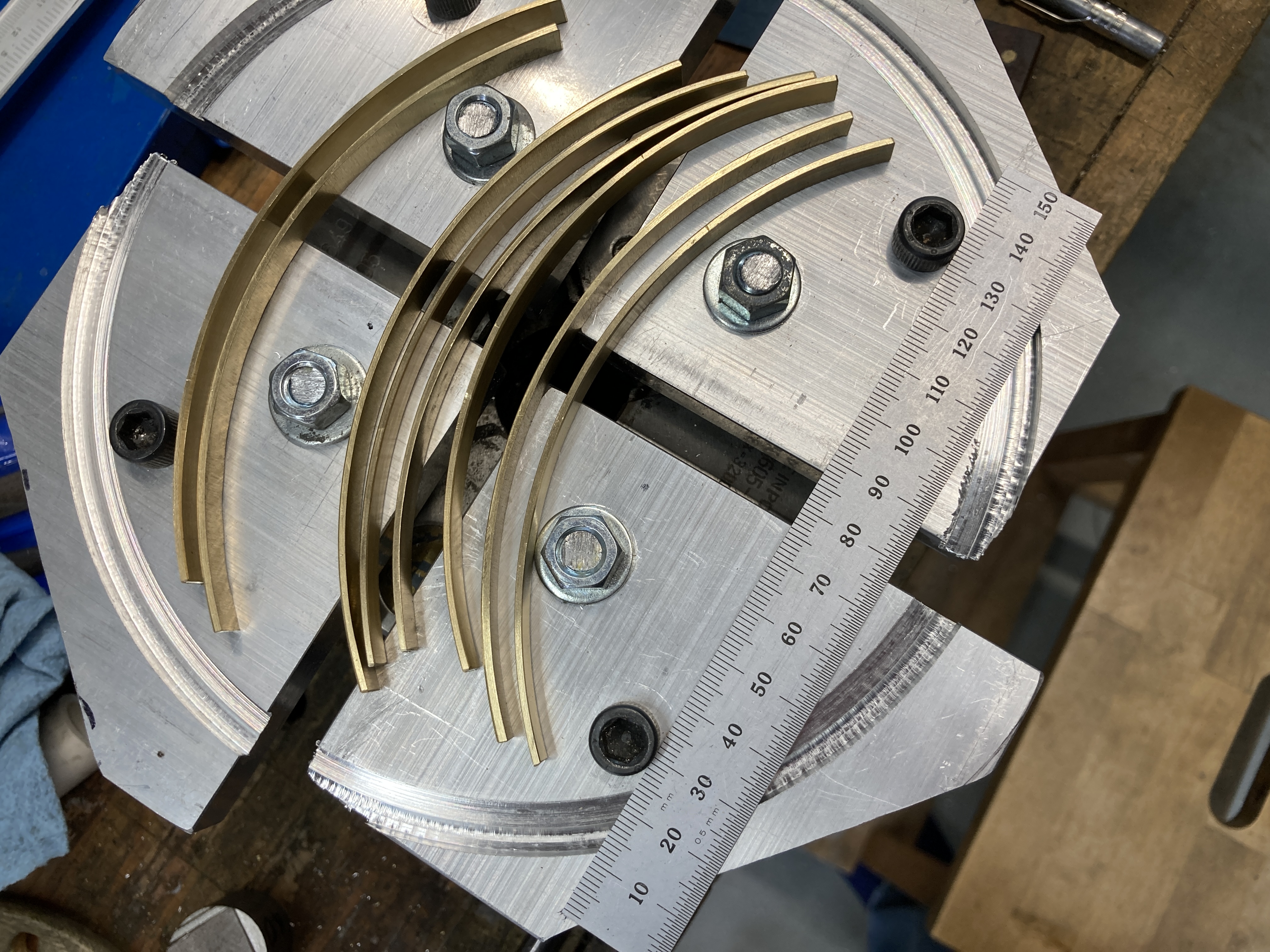
Each was then temporarily riveted to a pair of straight pieces and a small loop made of a section of copper pipe (which happened to be the right size, saving me the trouble of making my own rings). The whole assemblies were then silver soldered together. This is one step I somehow did not photograph...
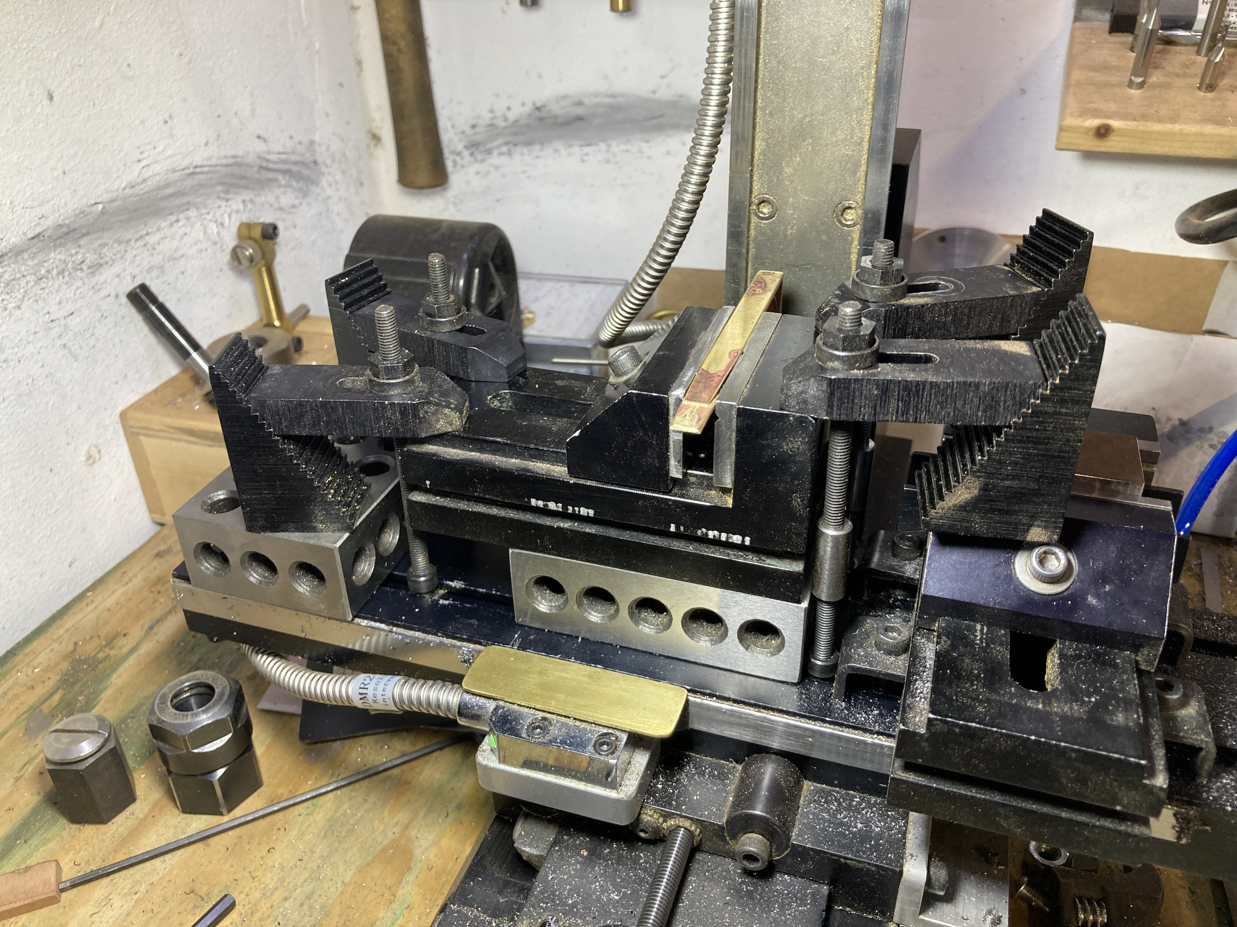
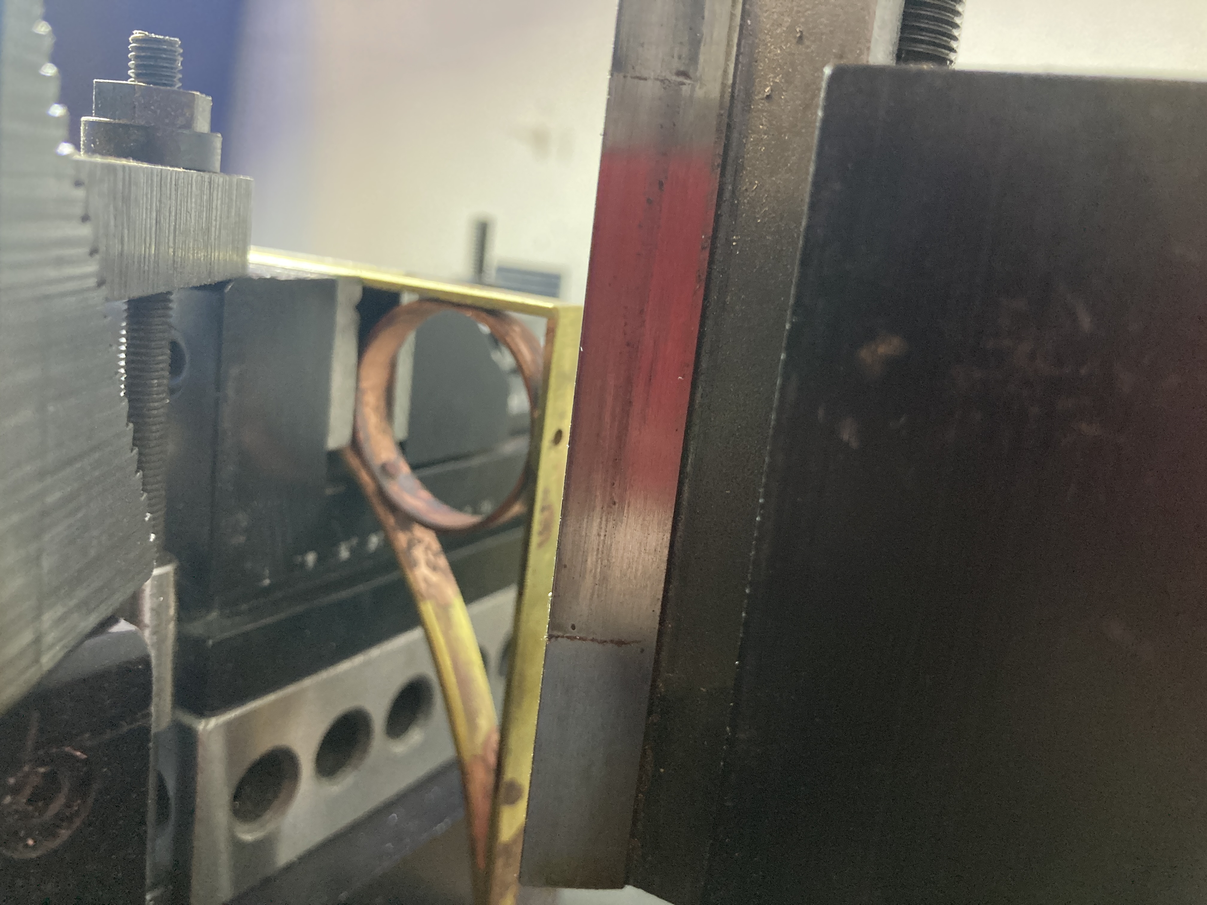
After soldering, the rivets near the ends and where the small lopps meet the flat sections were drilled out to make room for the screws that would eventually be used to attach the brackets to the wood structure. Drilling those holes required some interesting setups on my small milling machine! And yes, I do have a bigger machine that would be better suited for this task, but I enjoyed the challenge.
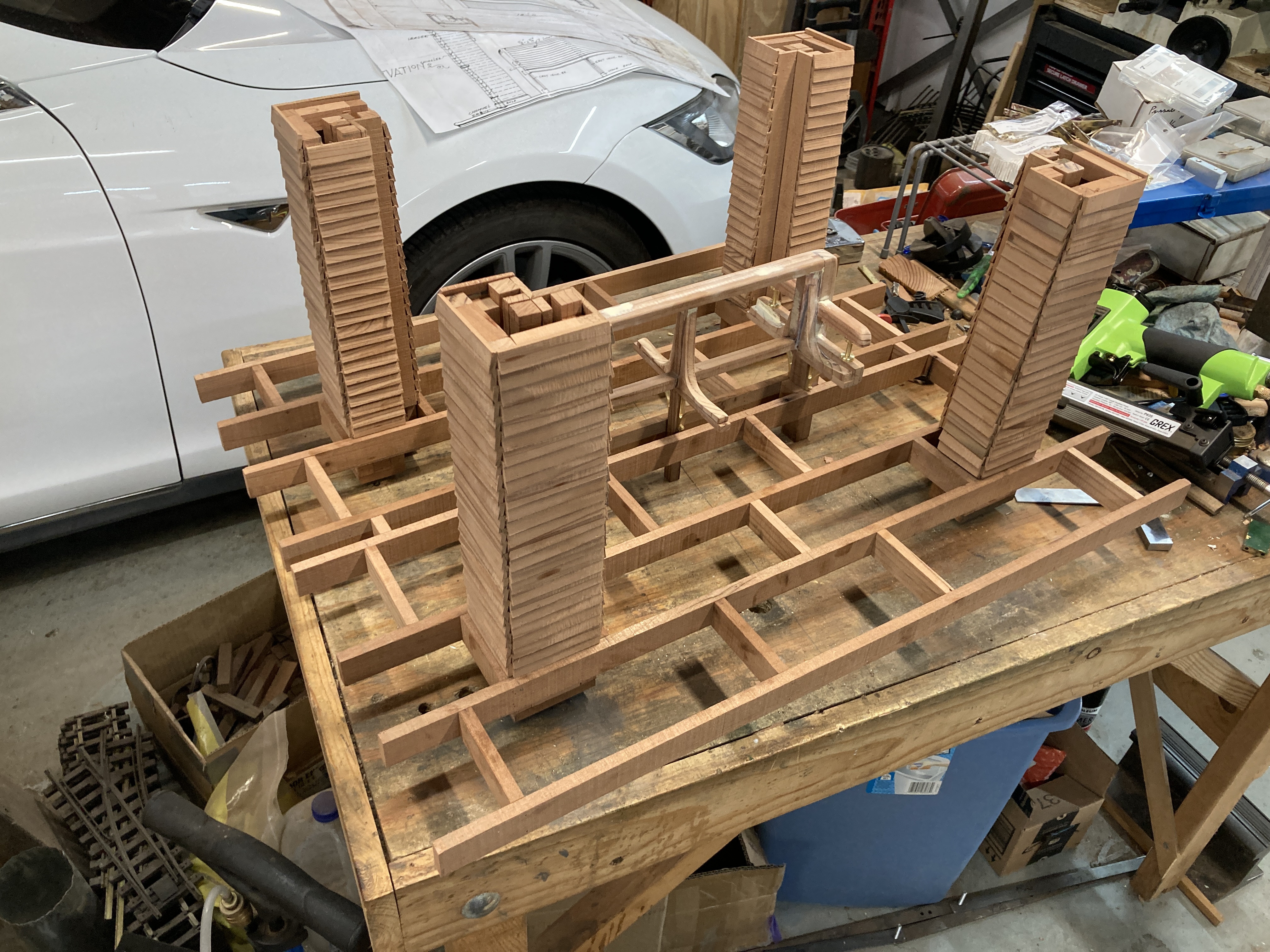
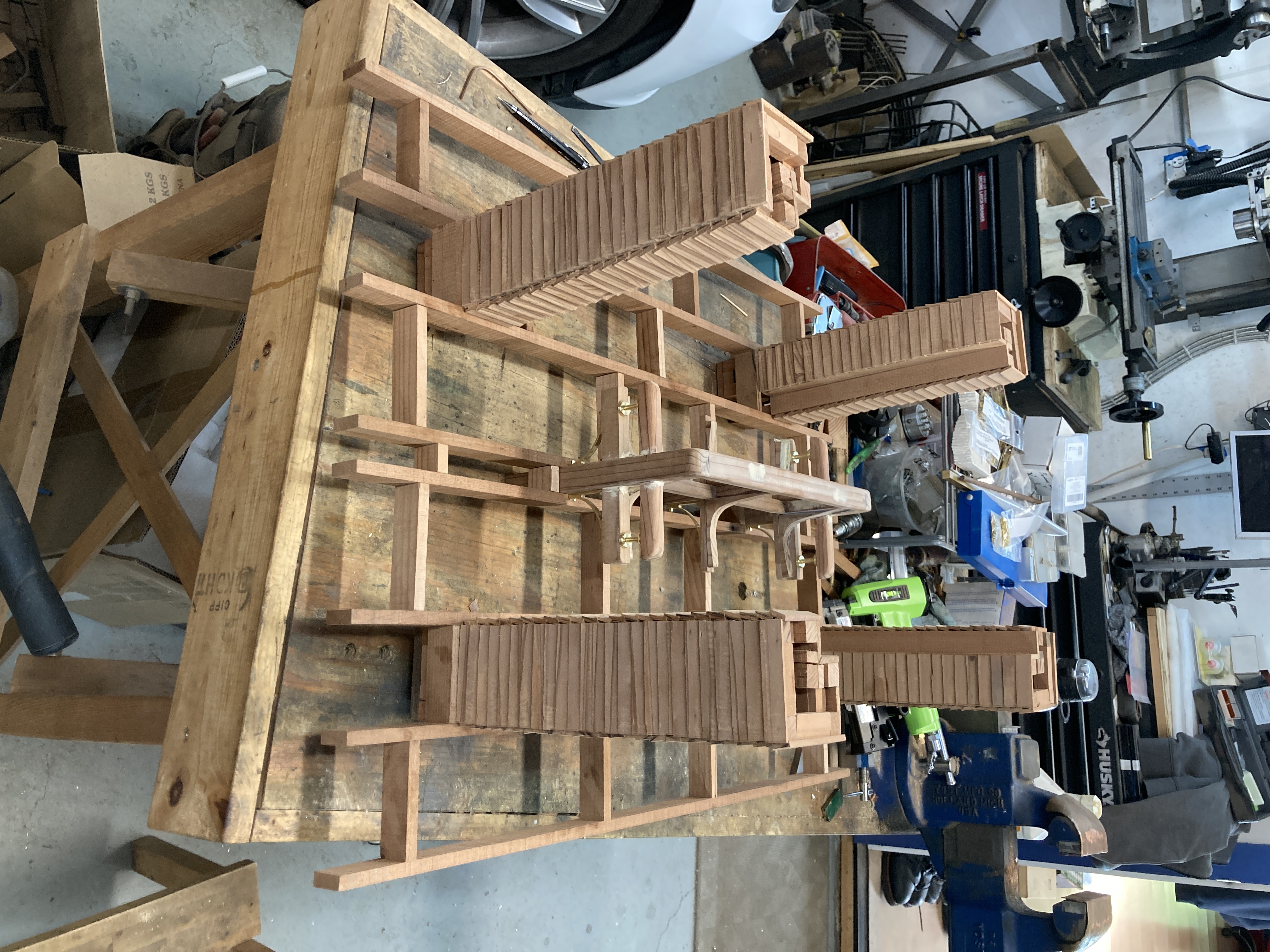
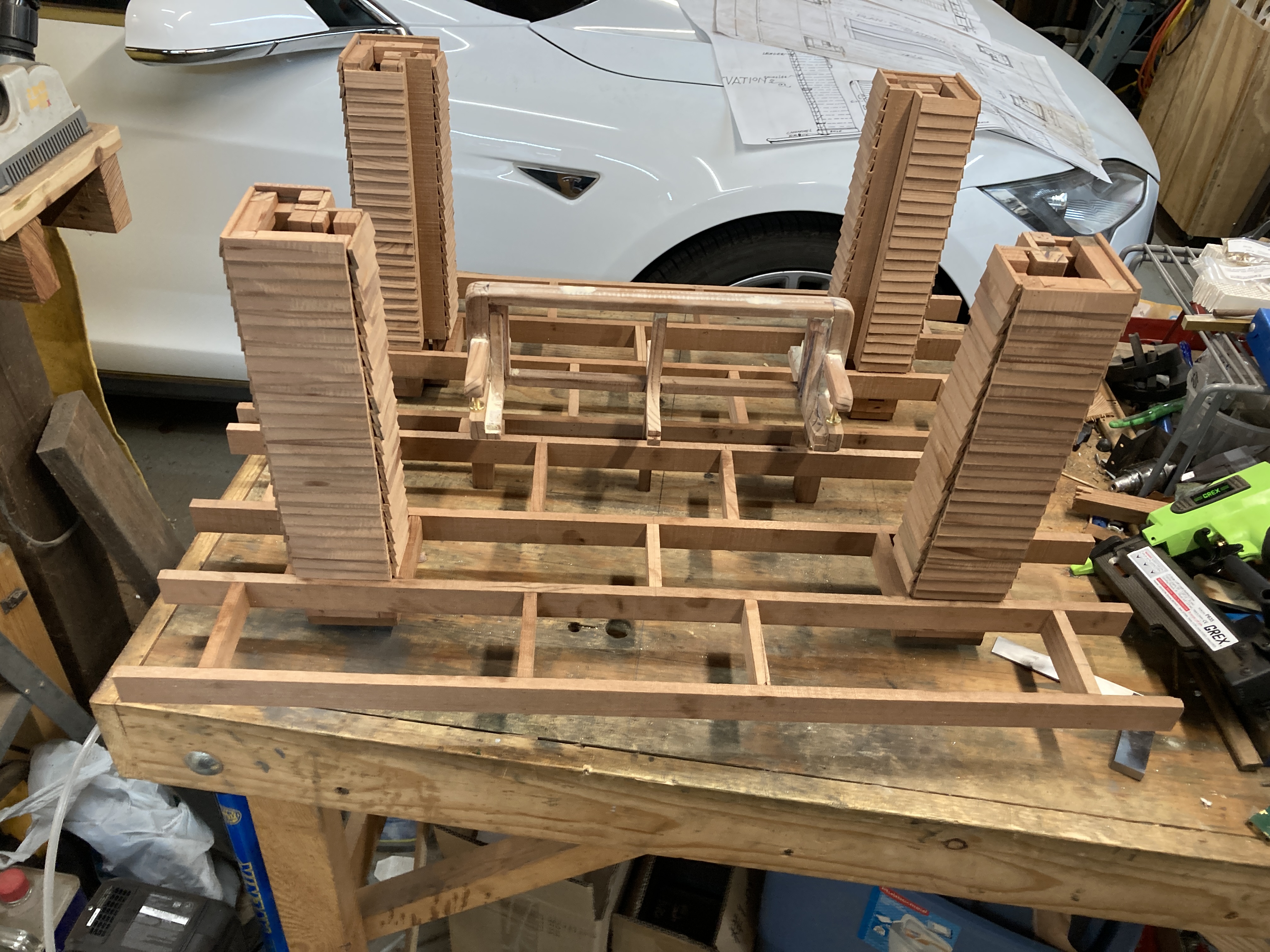
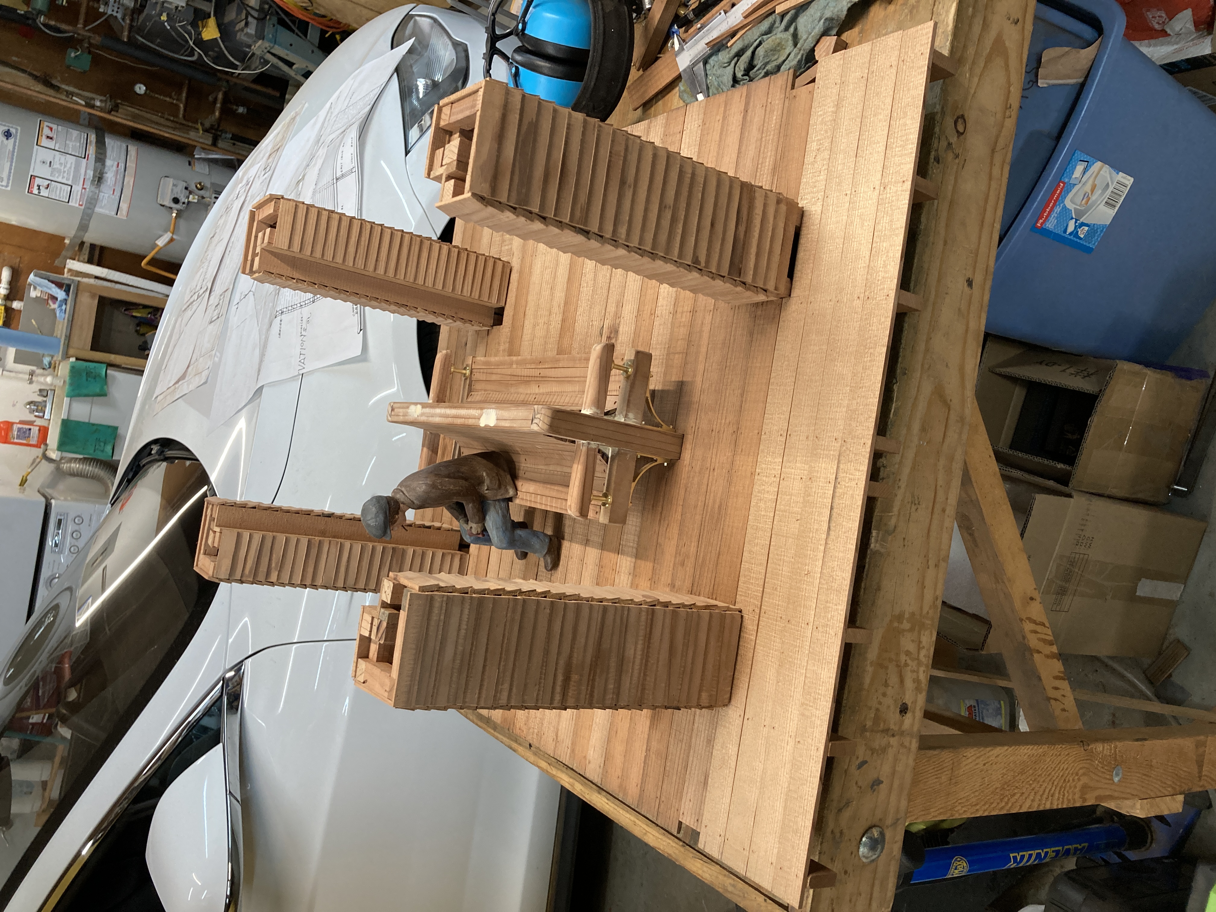
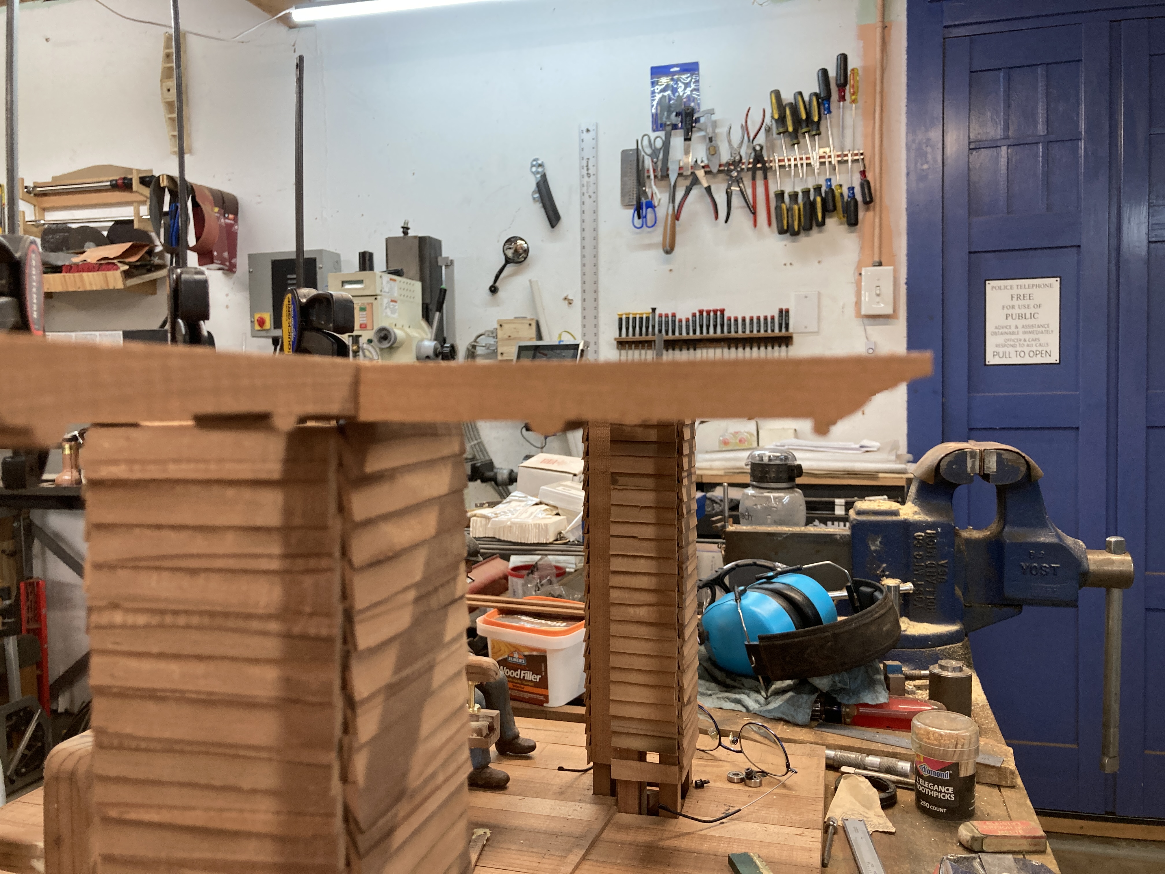
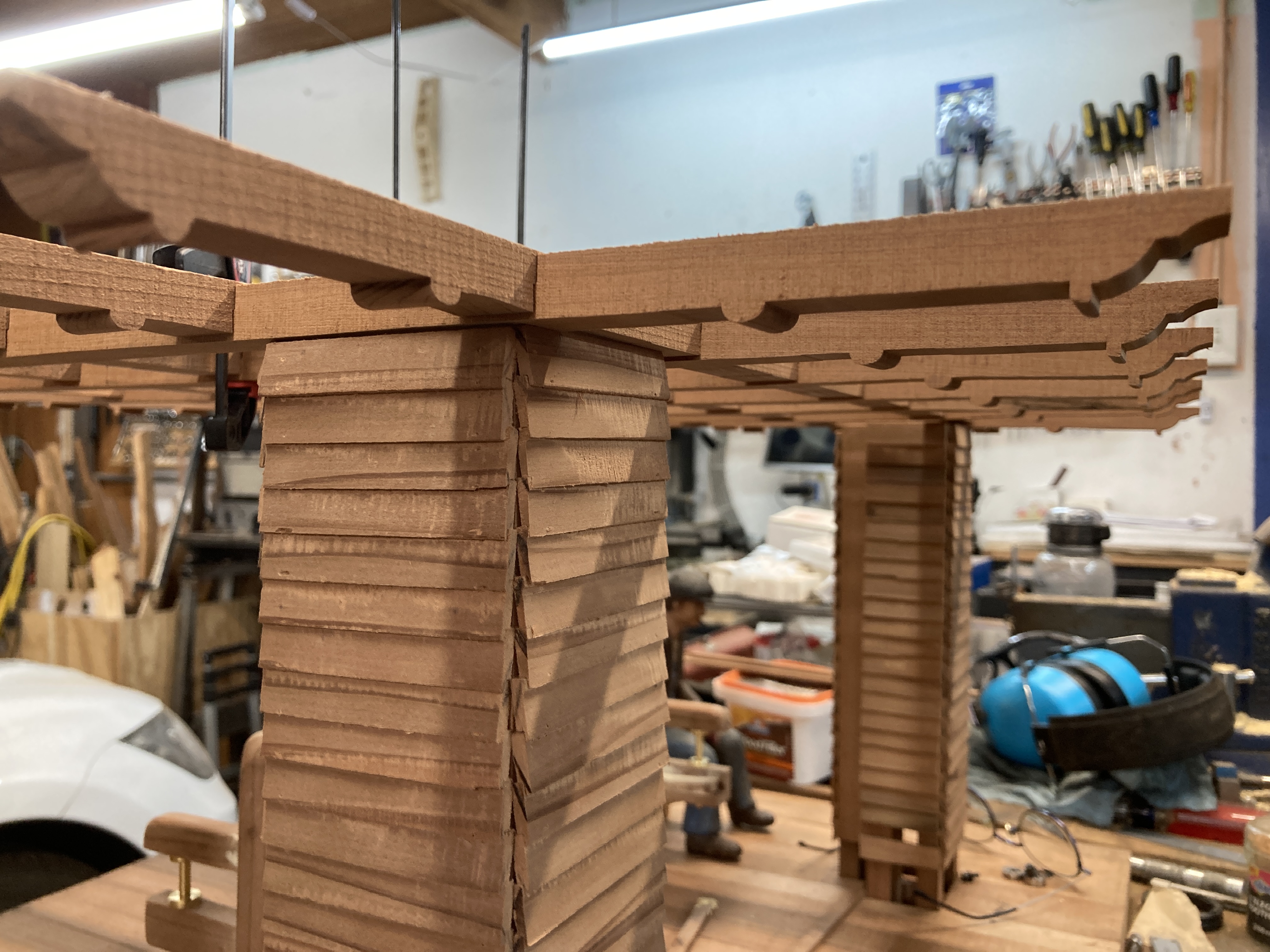
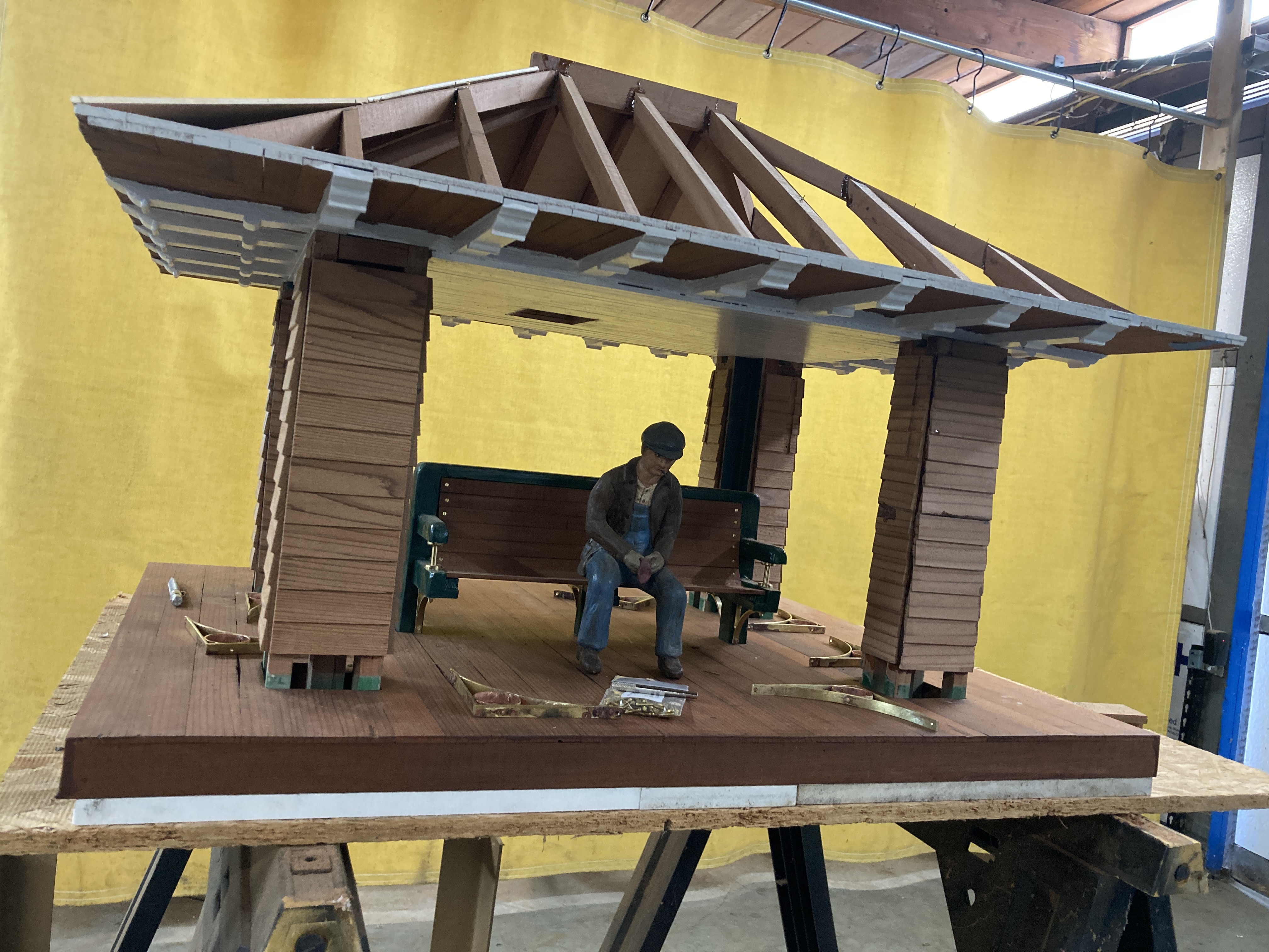
I then built the columns (twice!). They are fully framed like a real building using scale lumber I cut down on my bandsaw from 1x6" plank slavaged from an old deck. The first version of the columns used shiplap siding made from individual pieces but in the end I thought those pieces were too small for the scale.
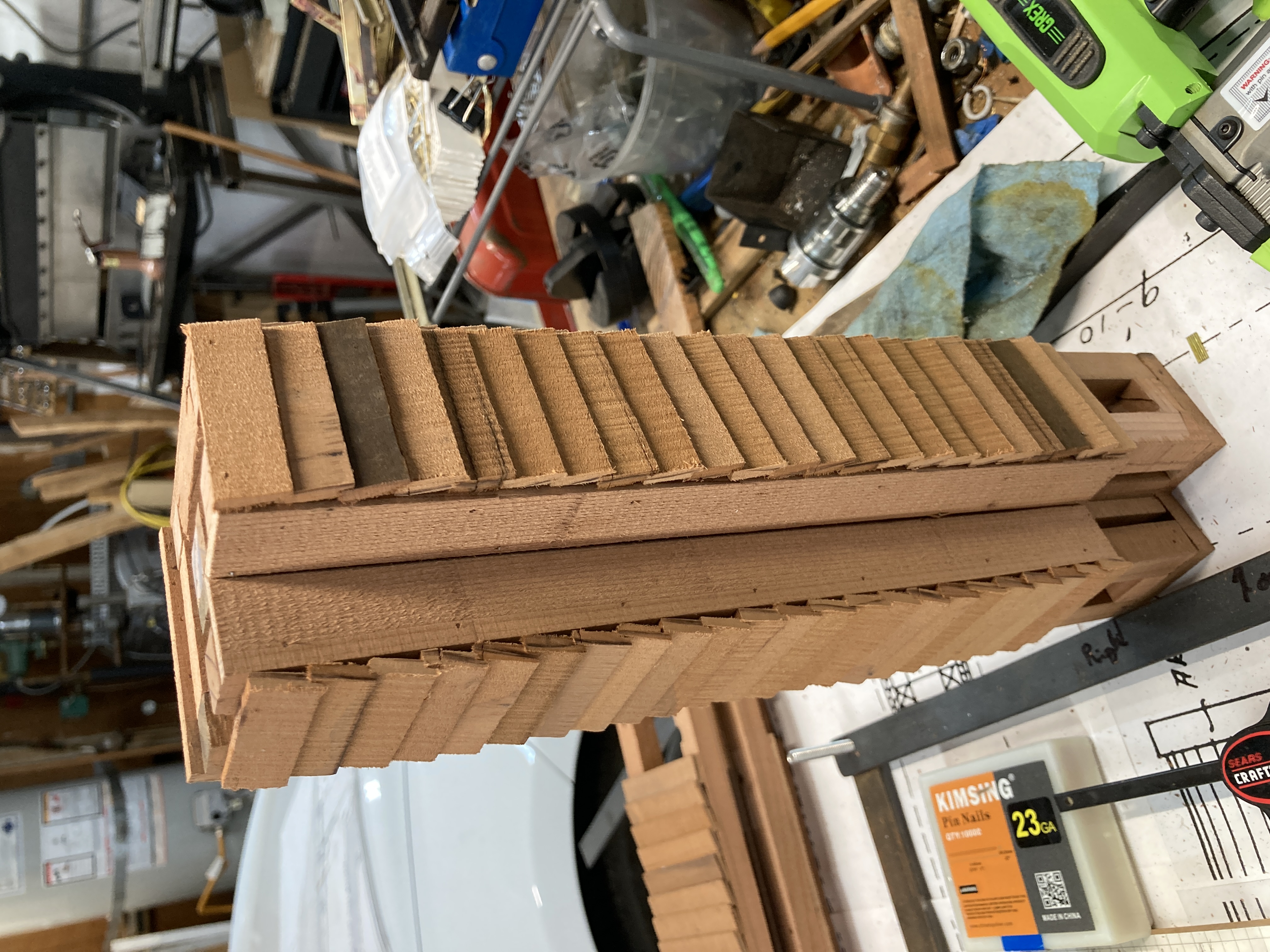
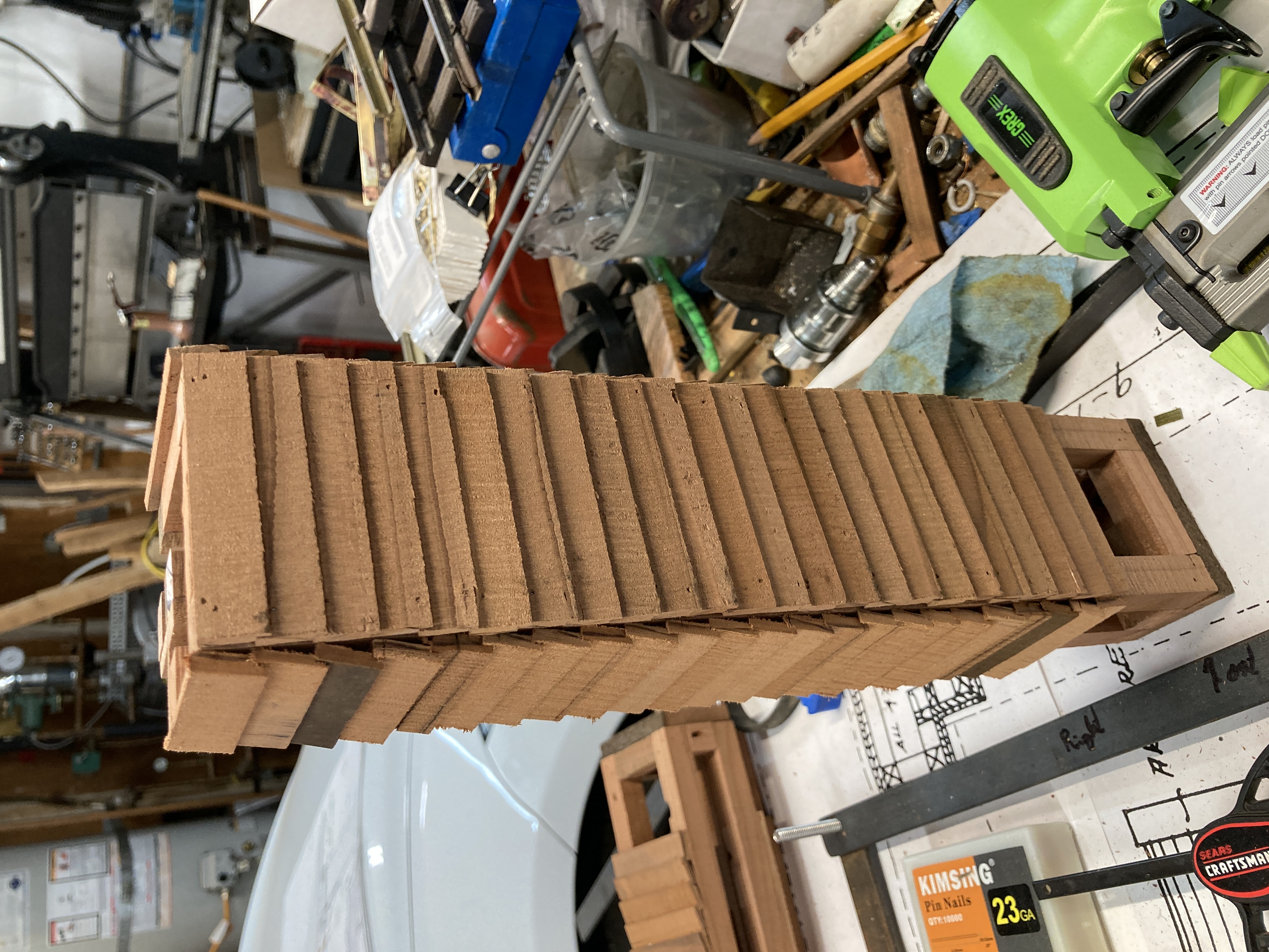
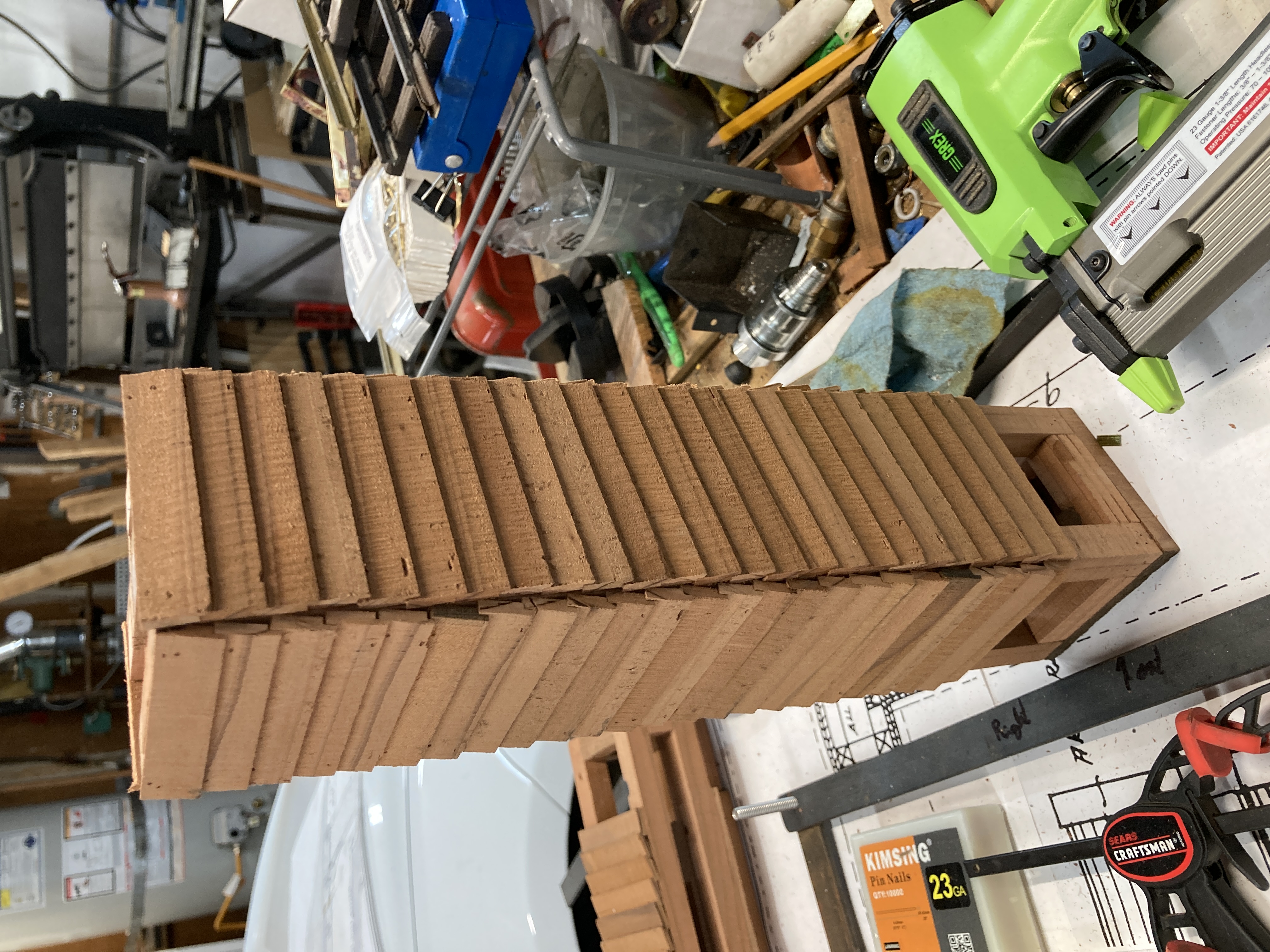
At that point the columns were entirely held together by 22 gauge nails. There were not eactly rigid! So for the do-over of the siding, I decided to mill panels out of solid pieces and glue them to the framing using epoxy. The photos here are out of order because it took me a while to decide to rebuild the columns and other work had already started by then. I don't have any photos of the setup on my big milling machine showing how I milled those panels. So here the result.
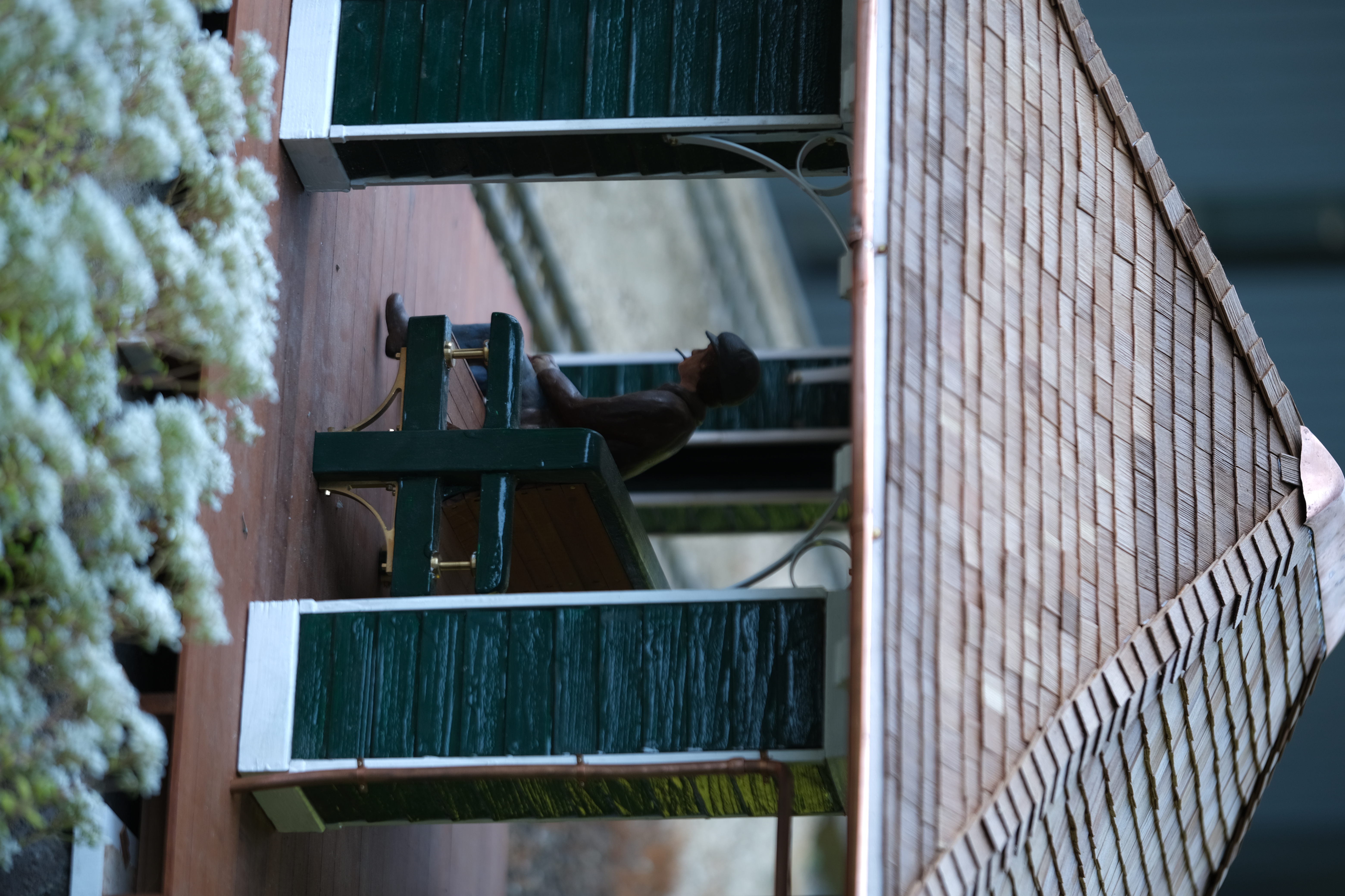
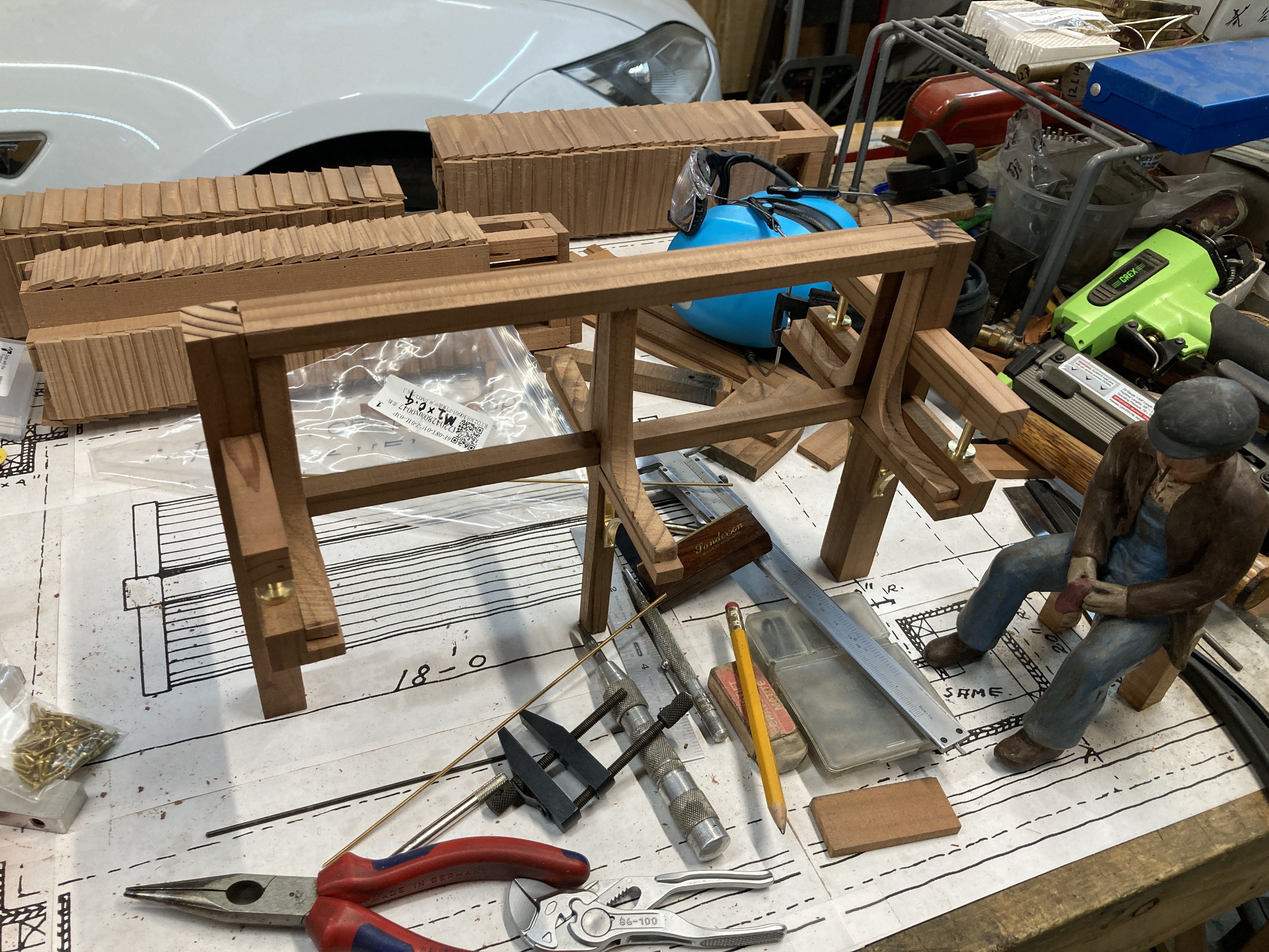
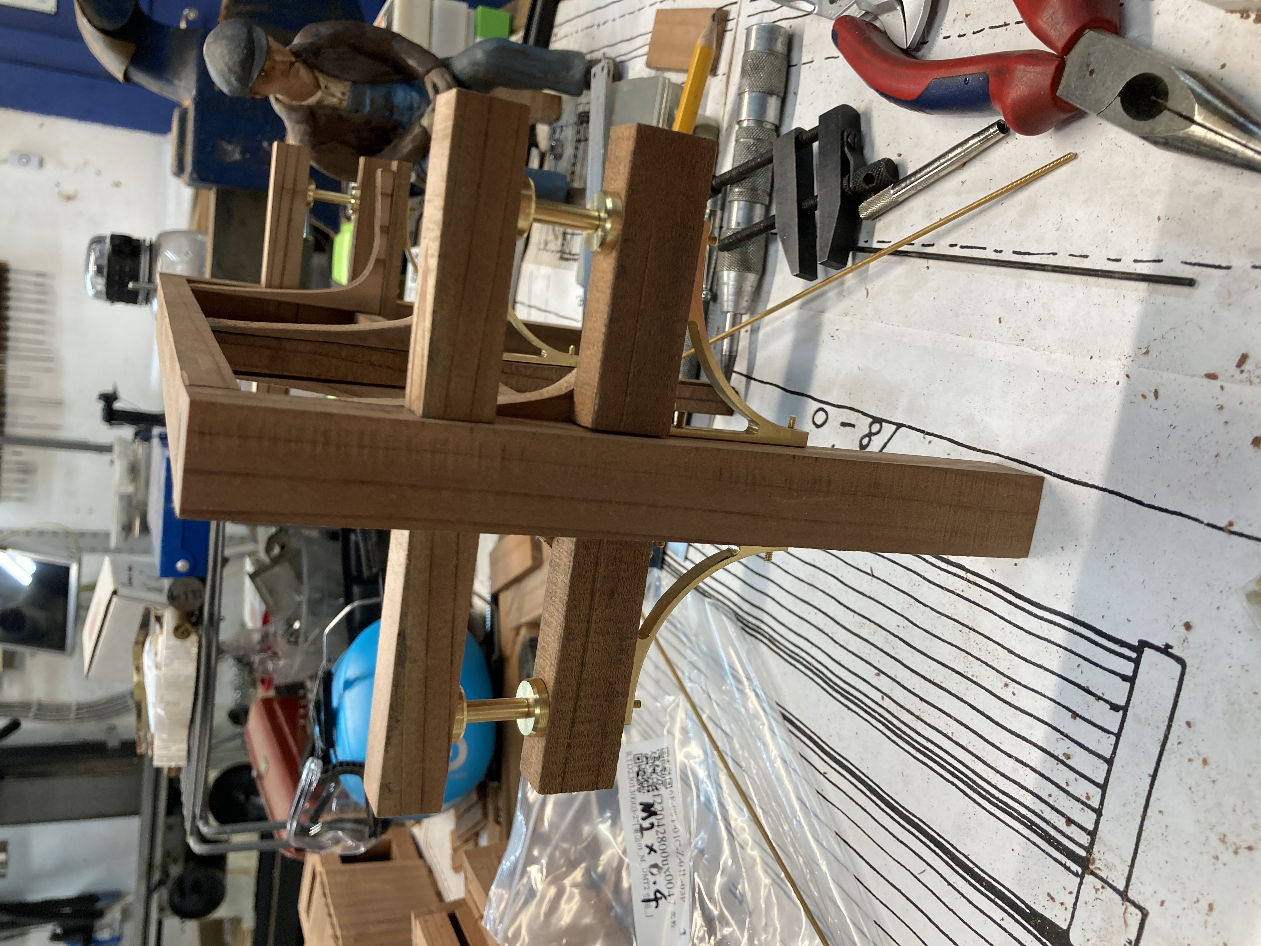
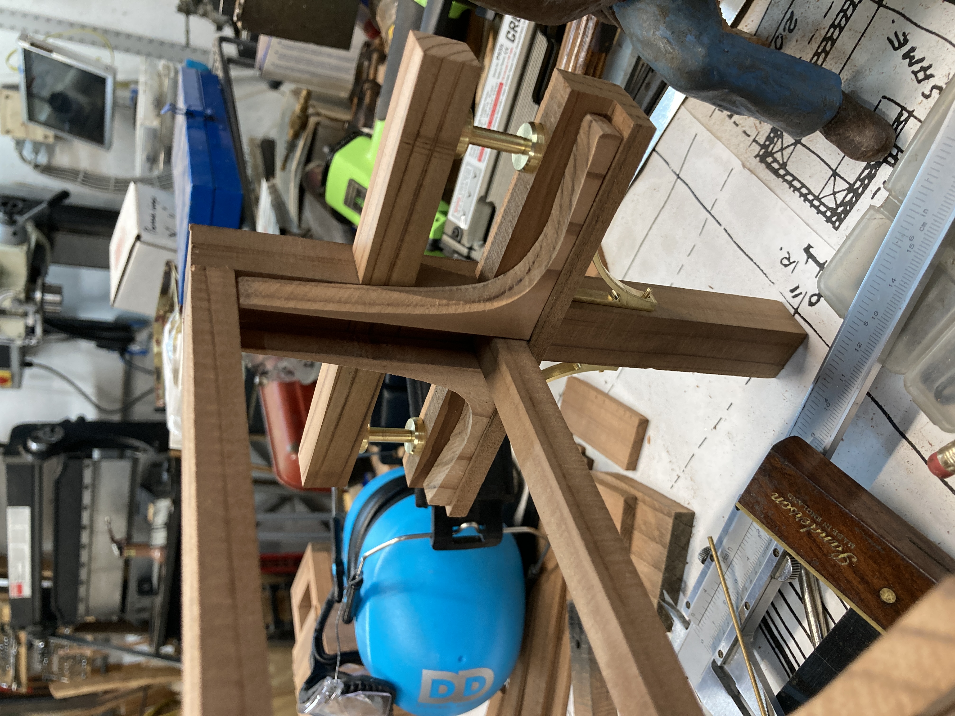
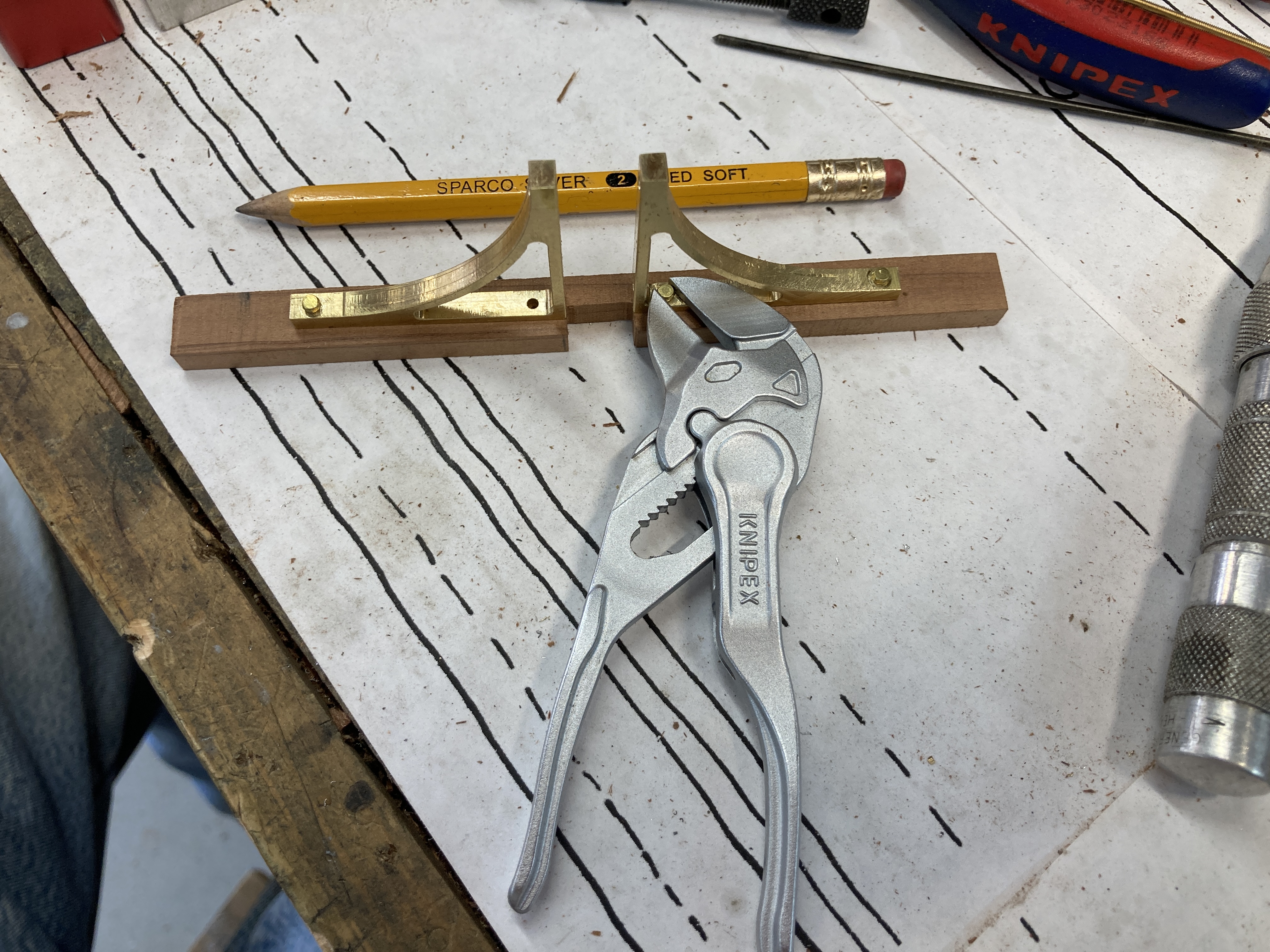
Going back in time, I built the double sided bench. The reason for building it early was that its legs would extend through the floor and would dictate the spacing of the under-floor structure. The first steps were to machine the brass parts (again, those would have been cast iron parts in the prototype). Milling the brackets involved a fun setup with the rotary table on the mill.
I then built out the rest of the bench's frame and assembled it using epoxy glue. This is one of those cases where one cannot have enough clamps!
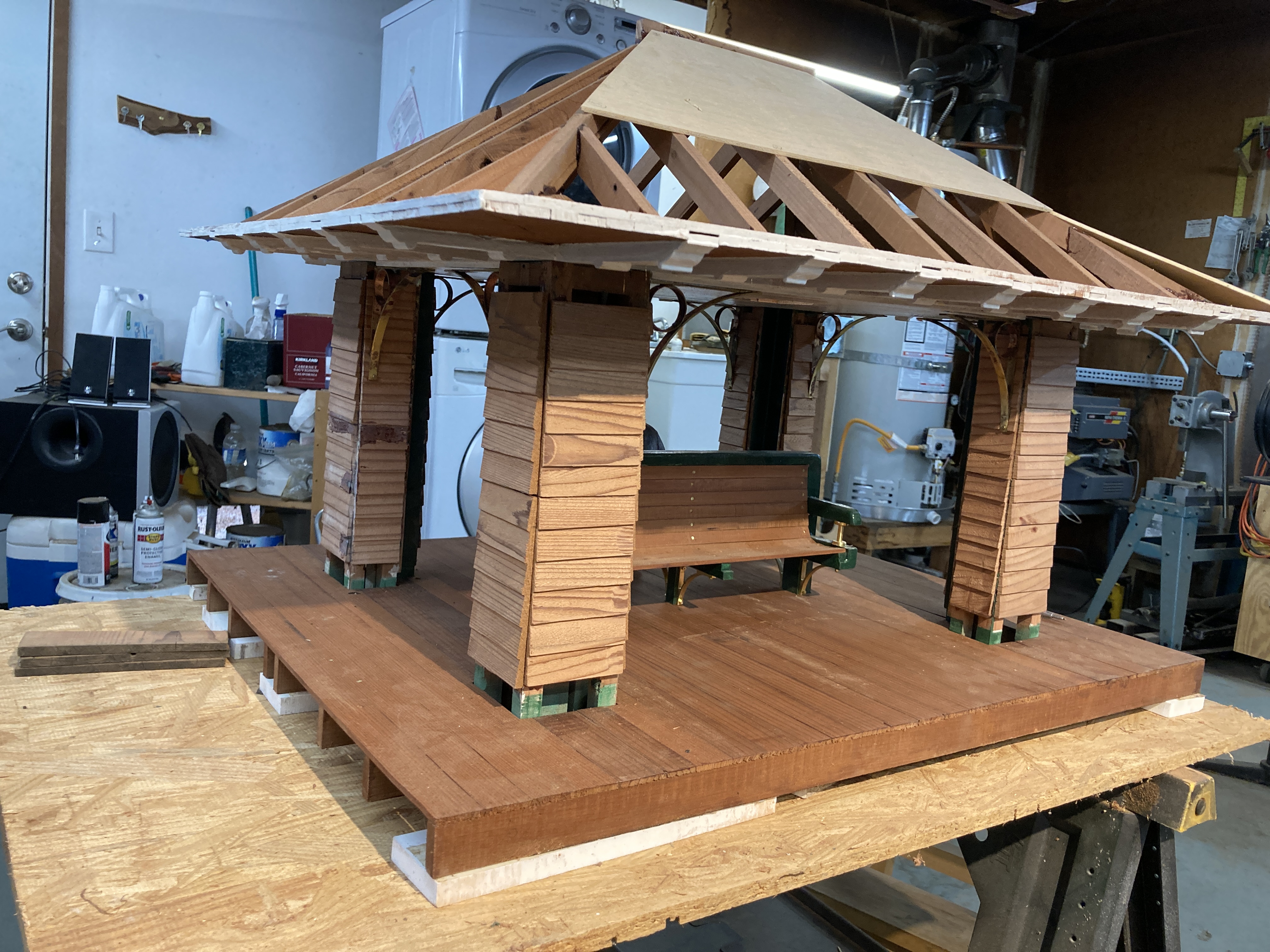
With the columns and bench basic structures ready, I built the framing for the floor.
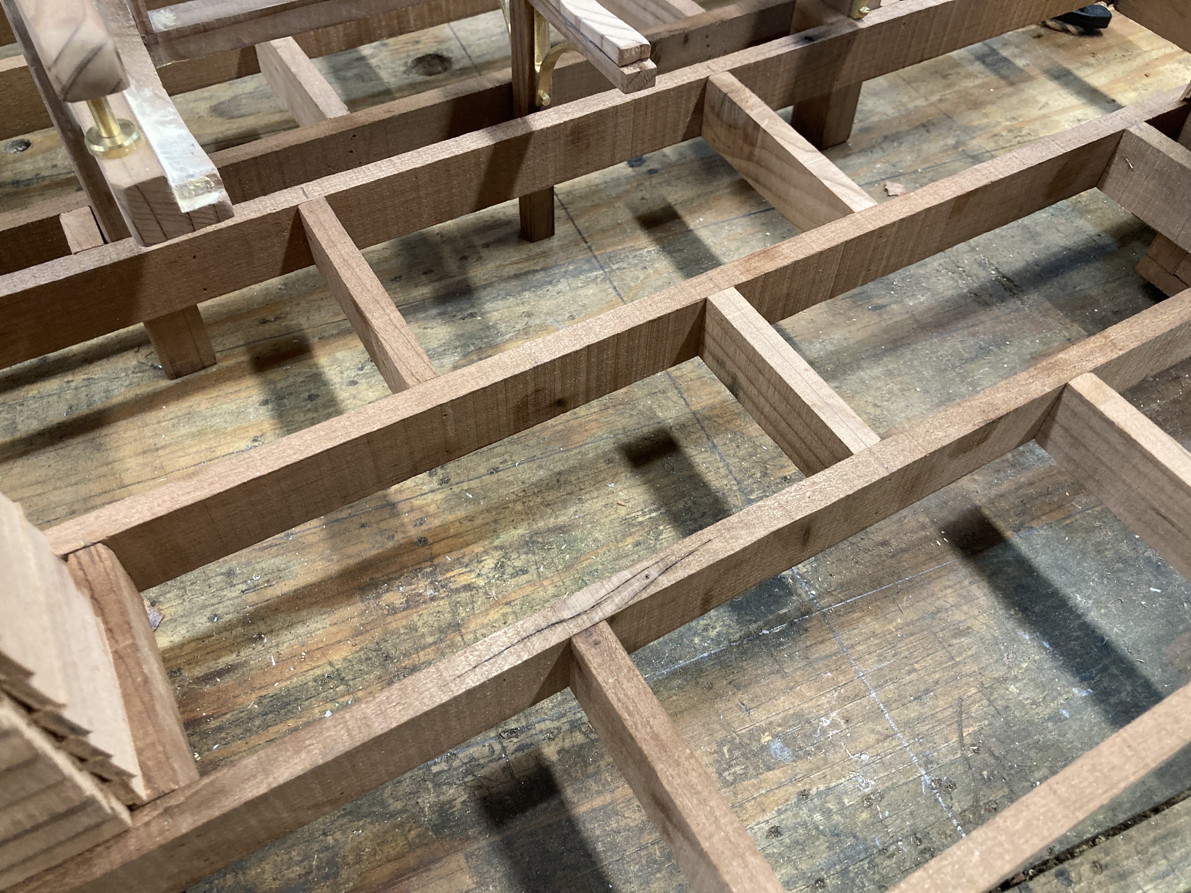
I then added the floor.
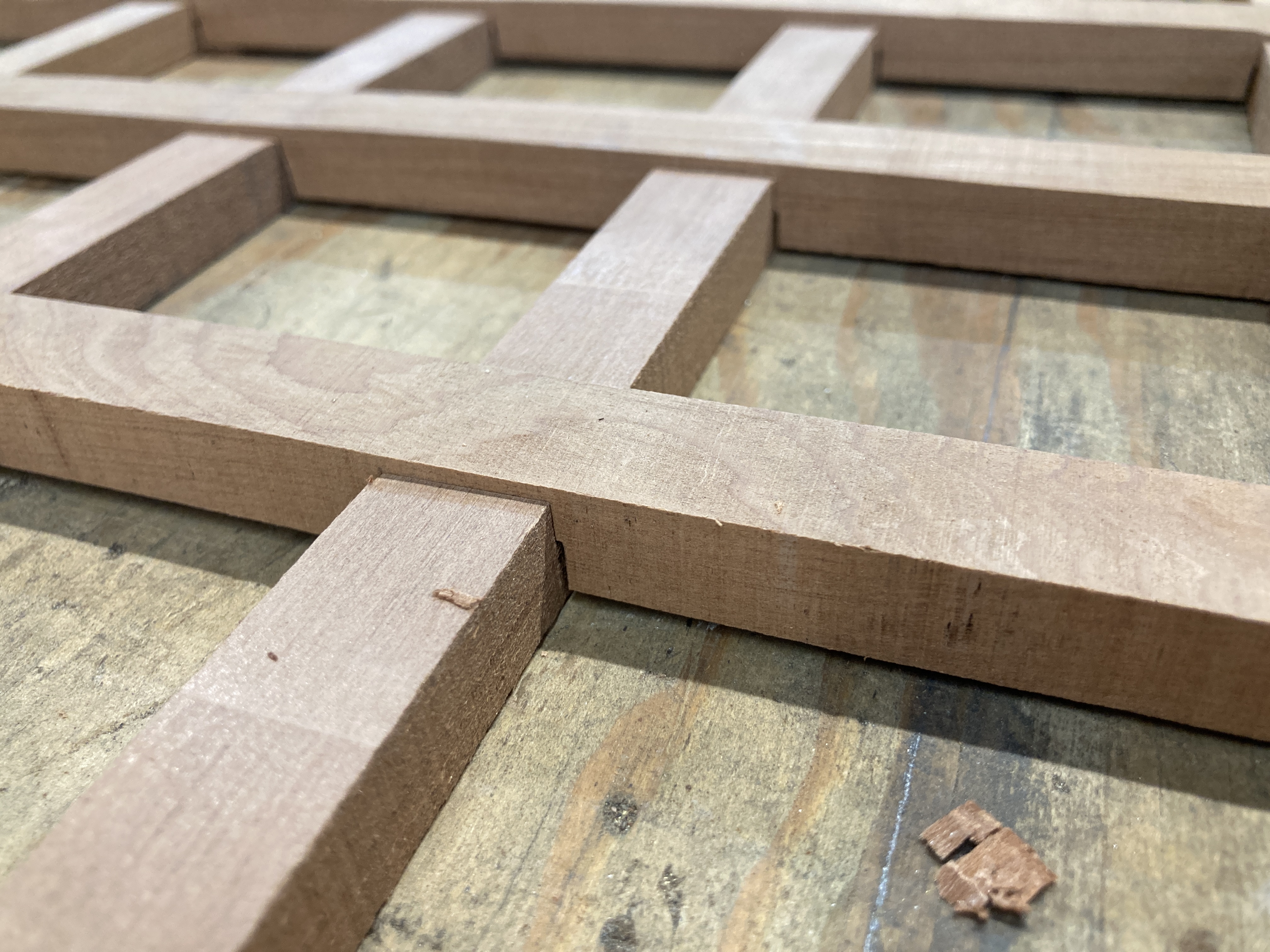
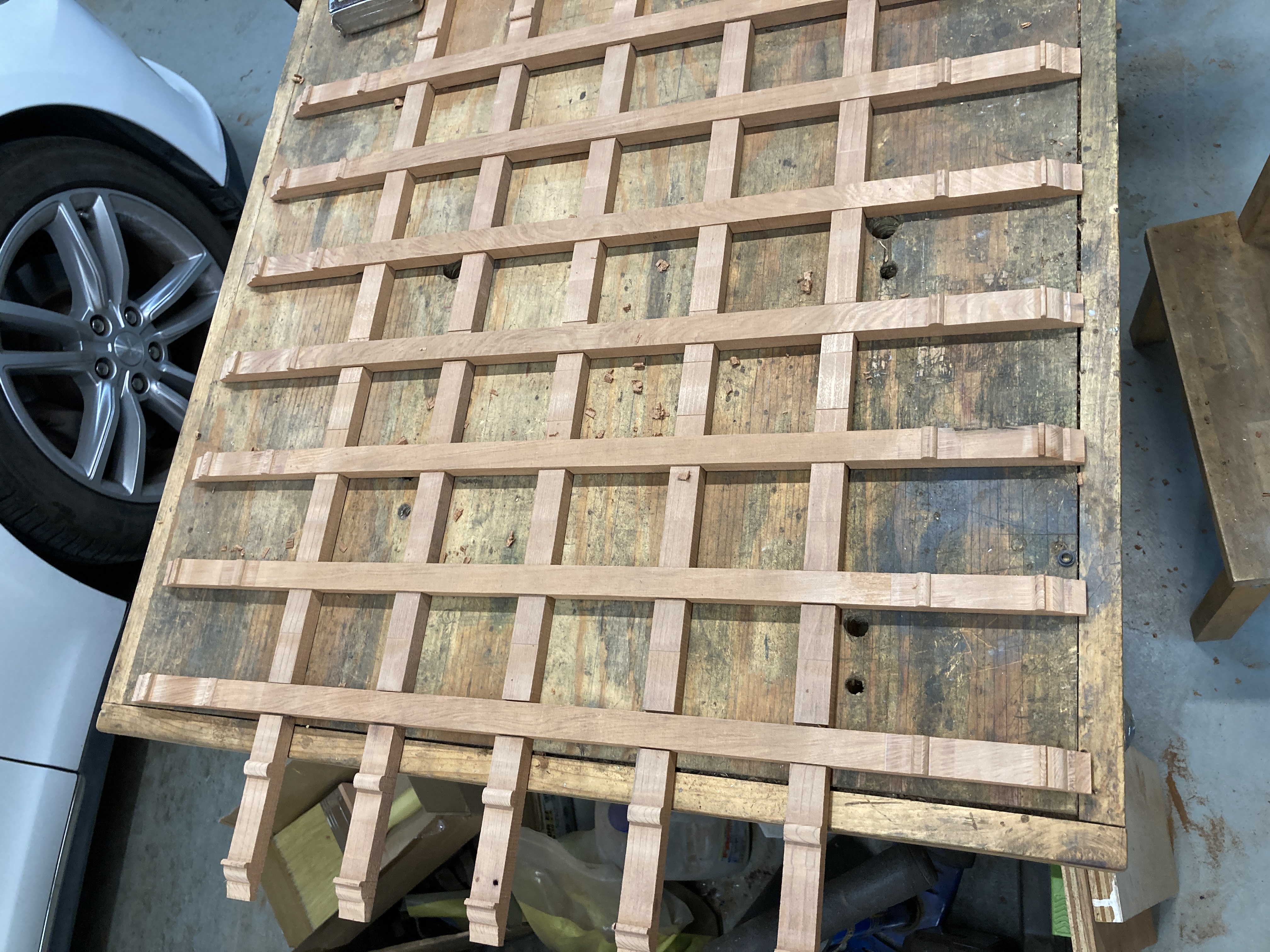
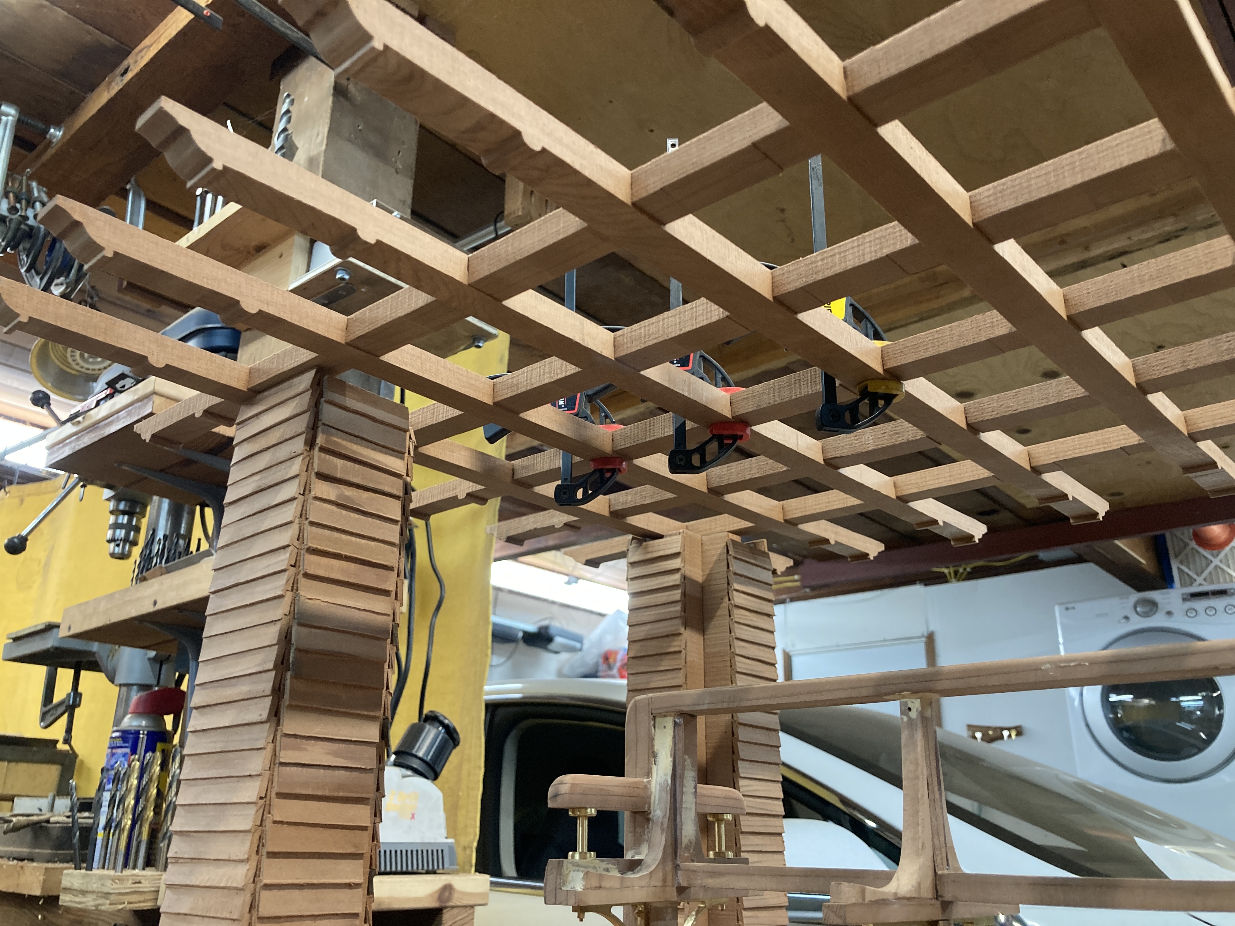
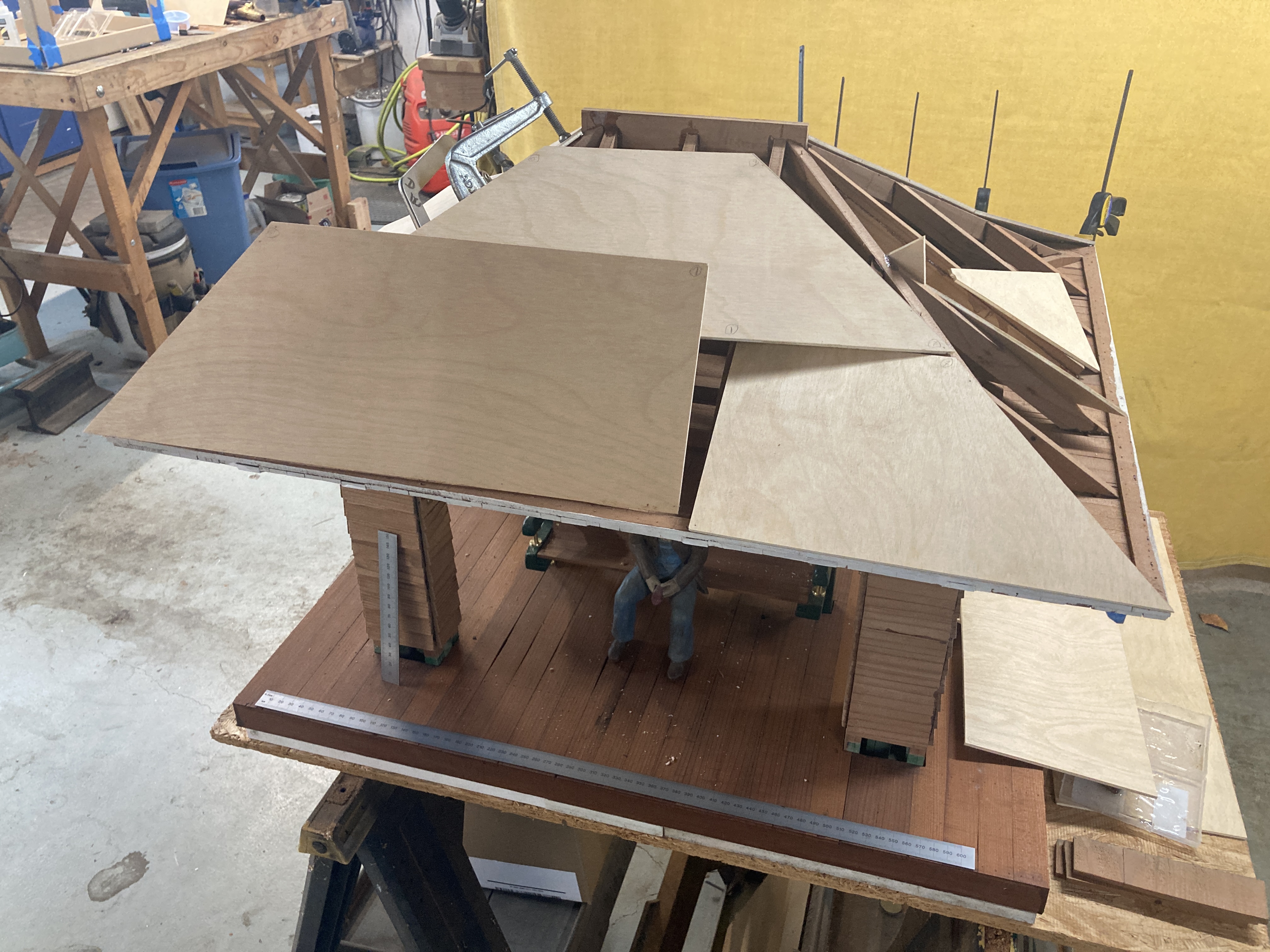
I then made a start on the roof structure. I wanted something robust, so I built a grid with half-lap joints which incorporated the corbel which would have been separate piece on the prototype.
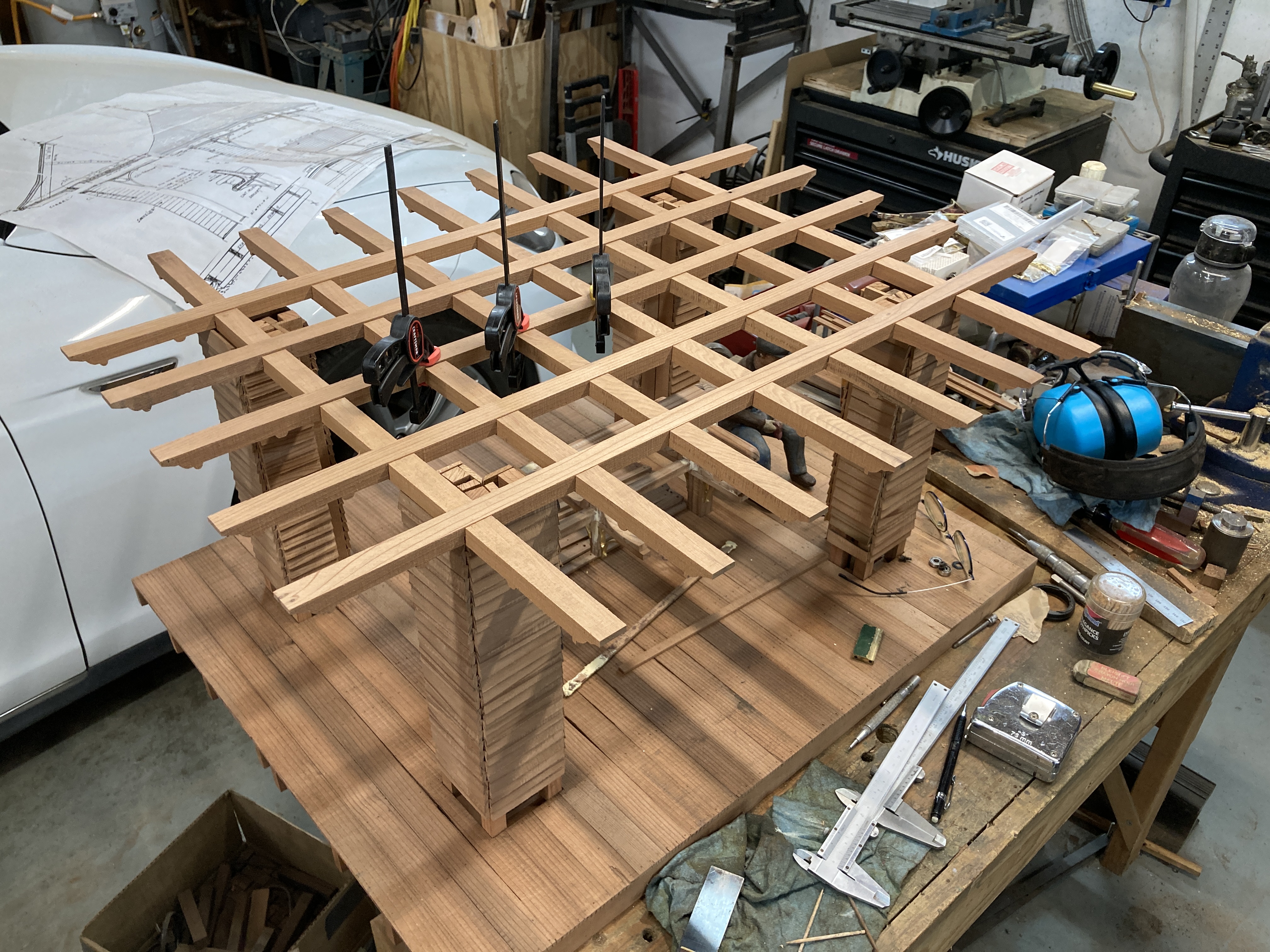
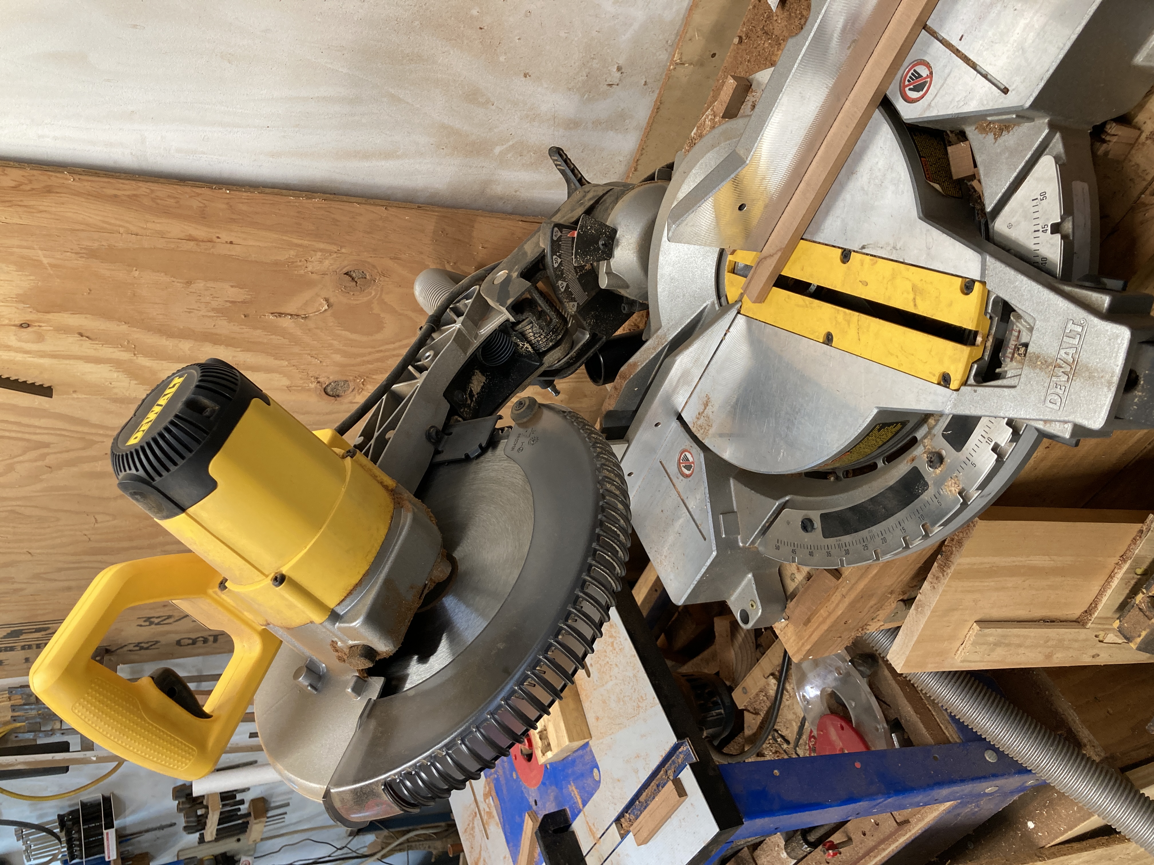
For the main roof structure, I followed the plans as best as I could. Cutting the corner rafters involved using the my mitter saw to its full extent!
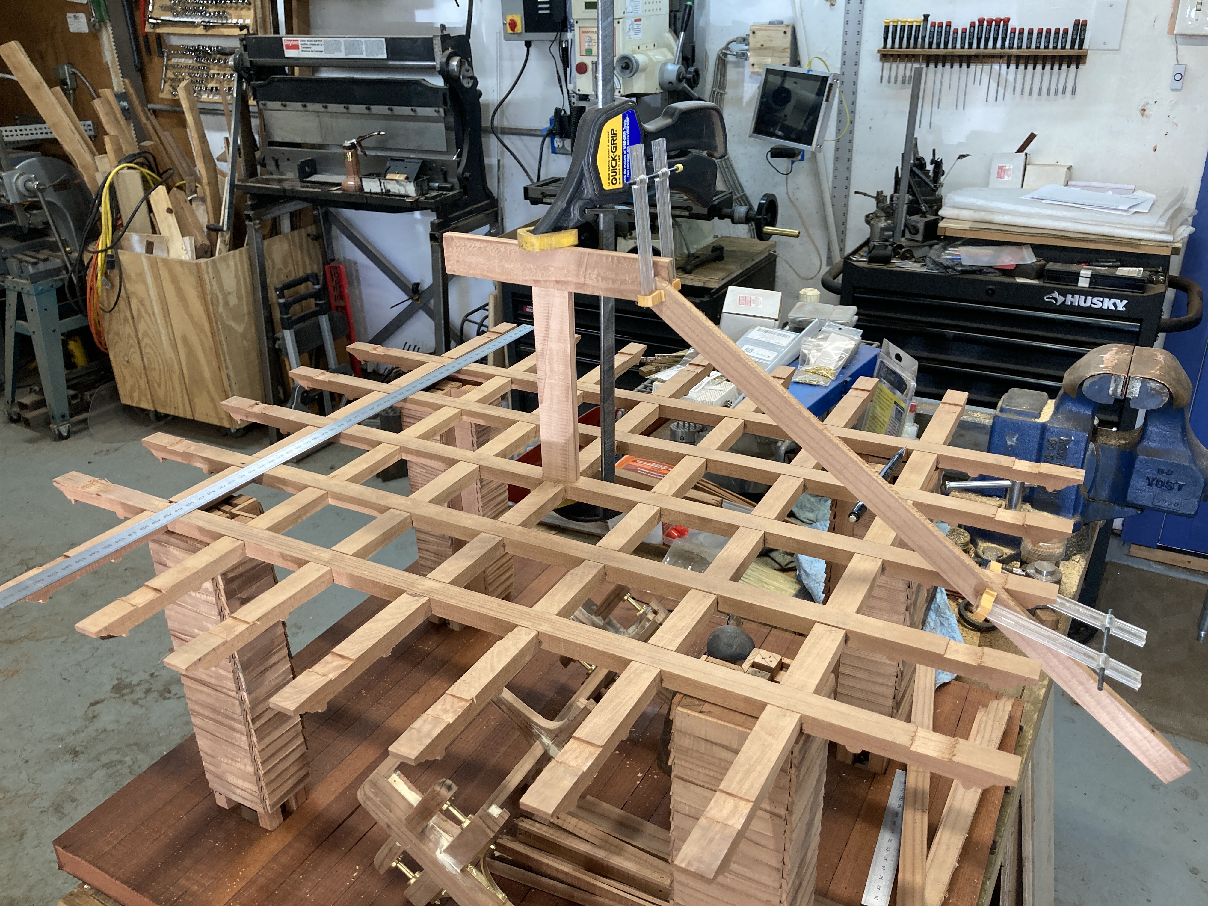
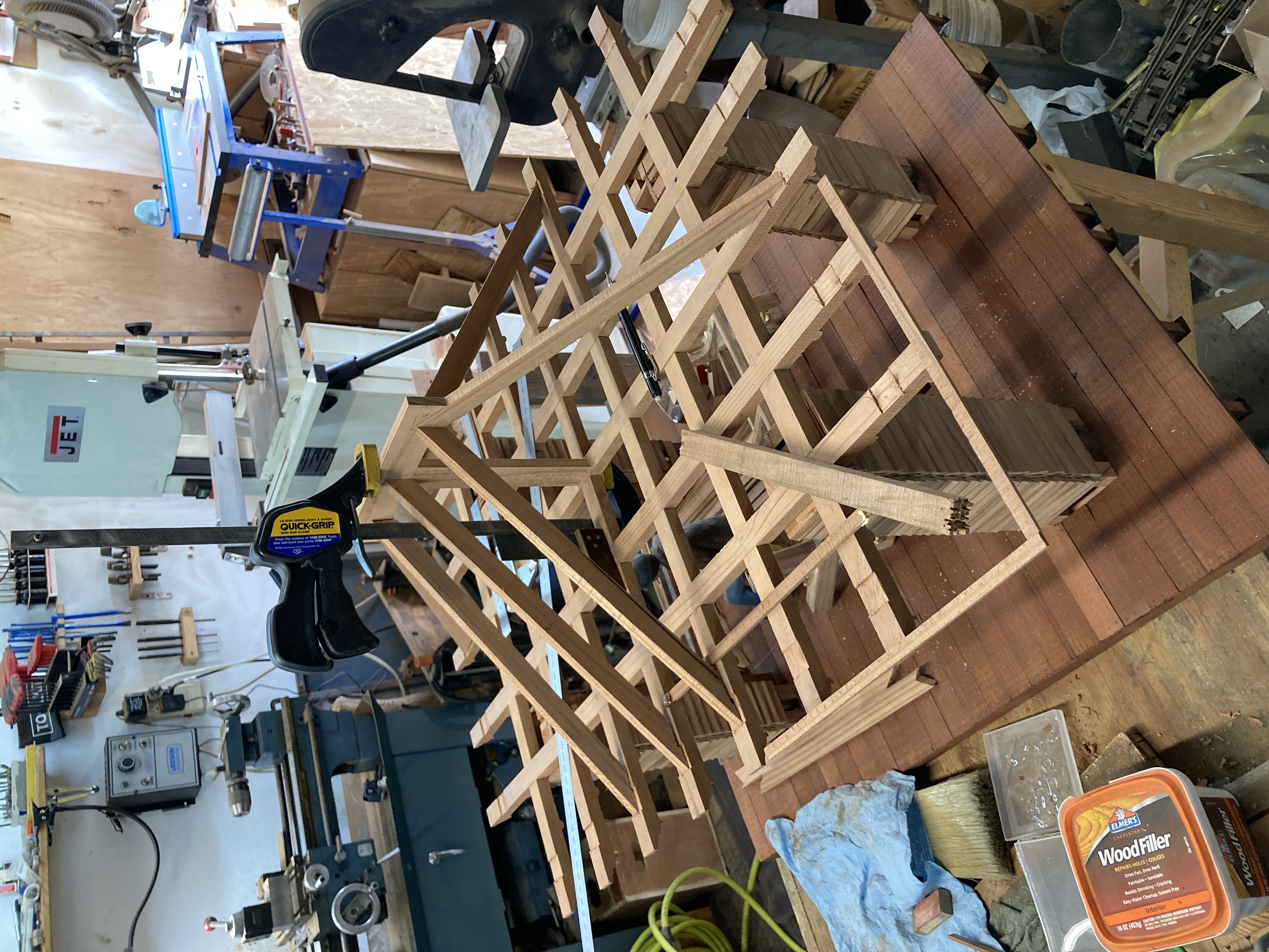
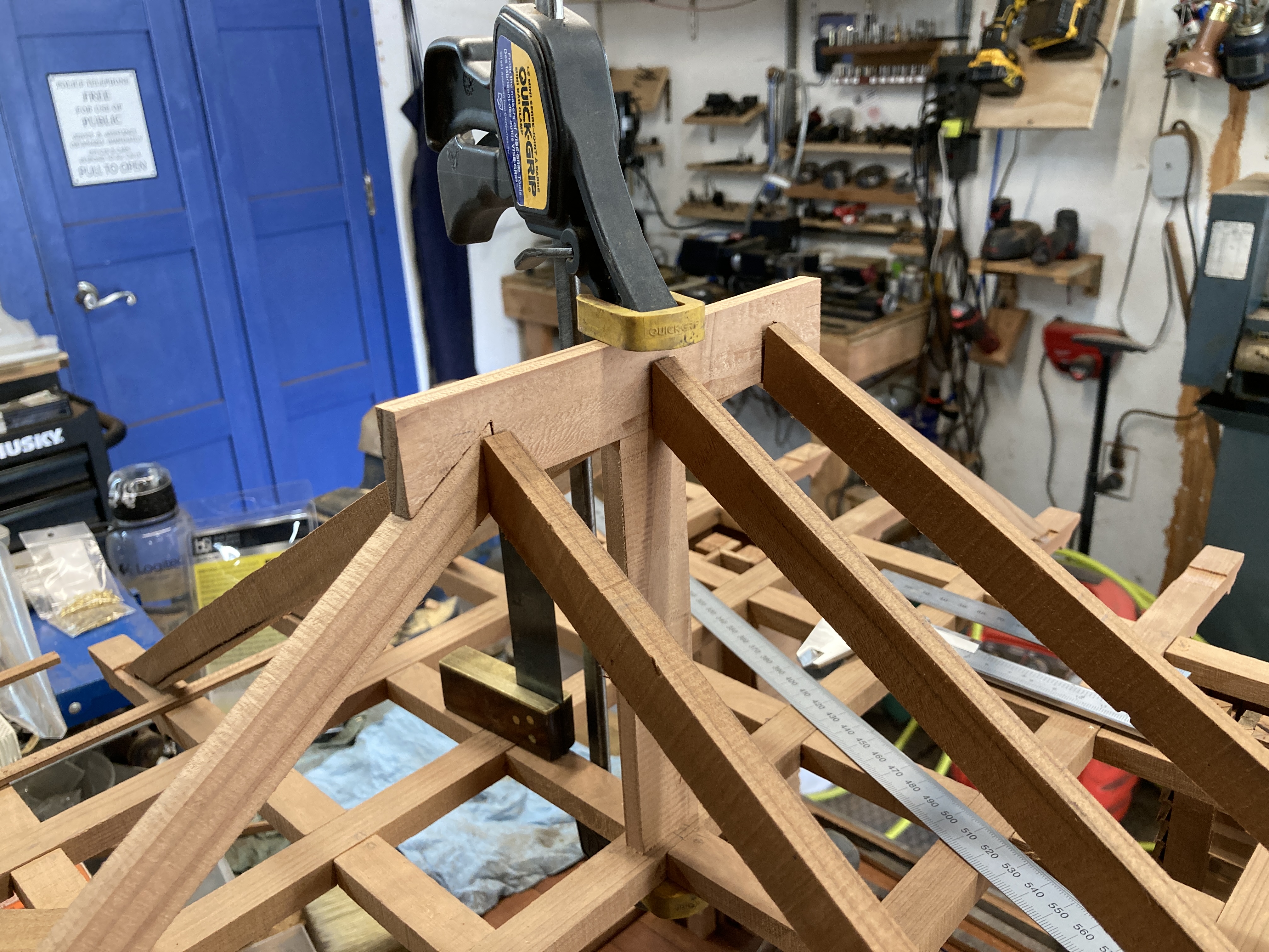
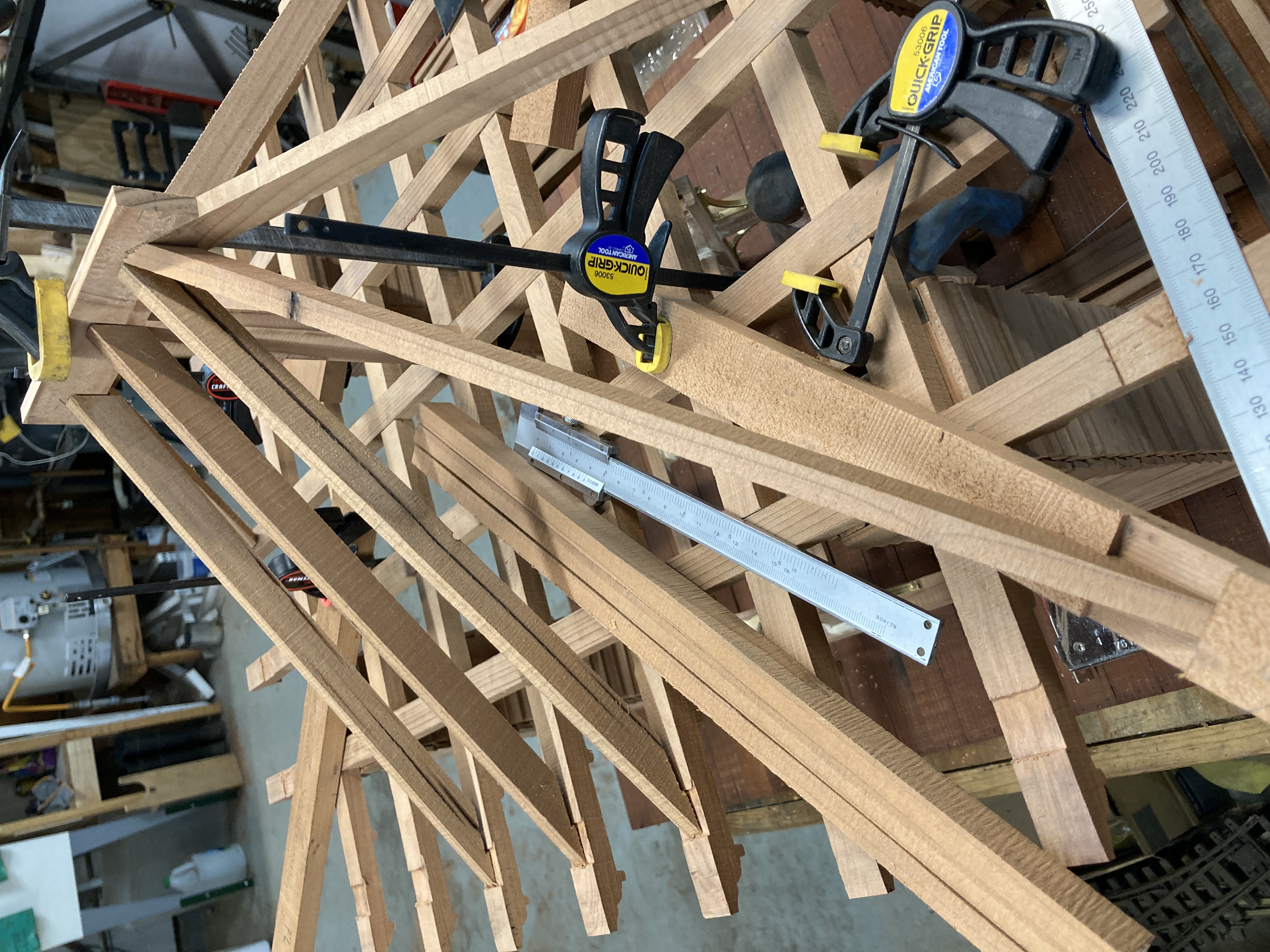
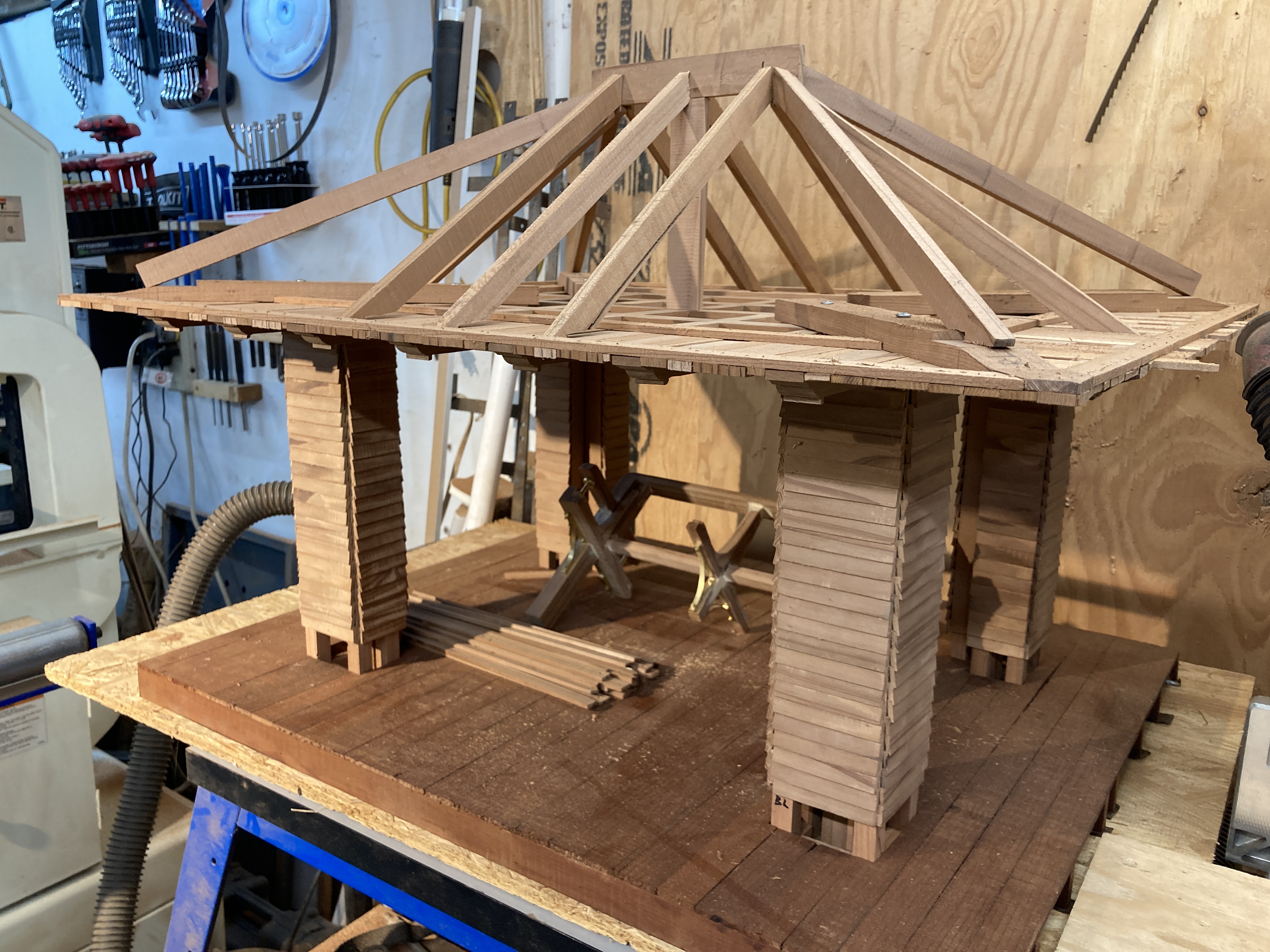
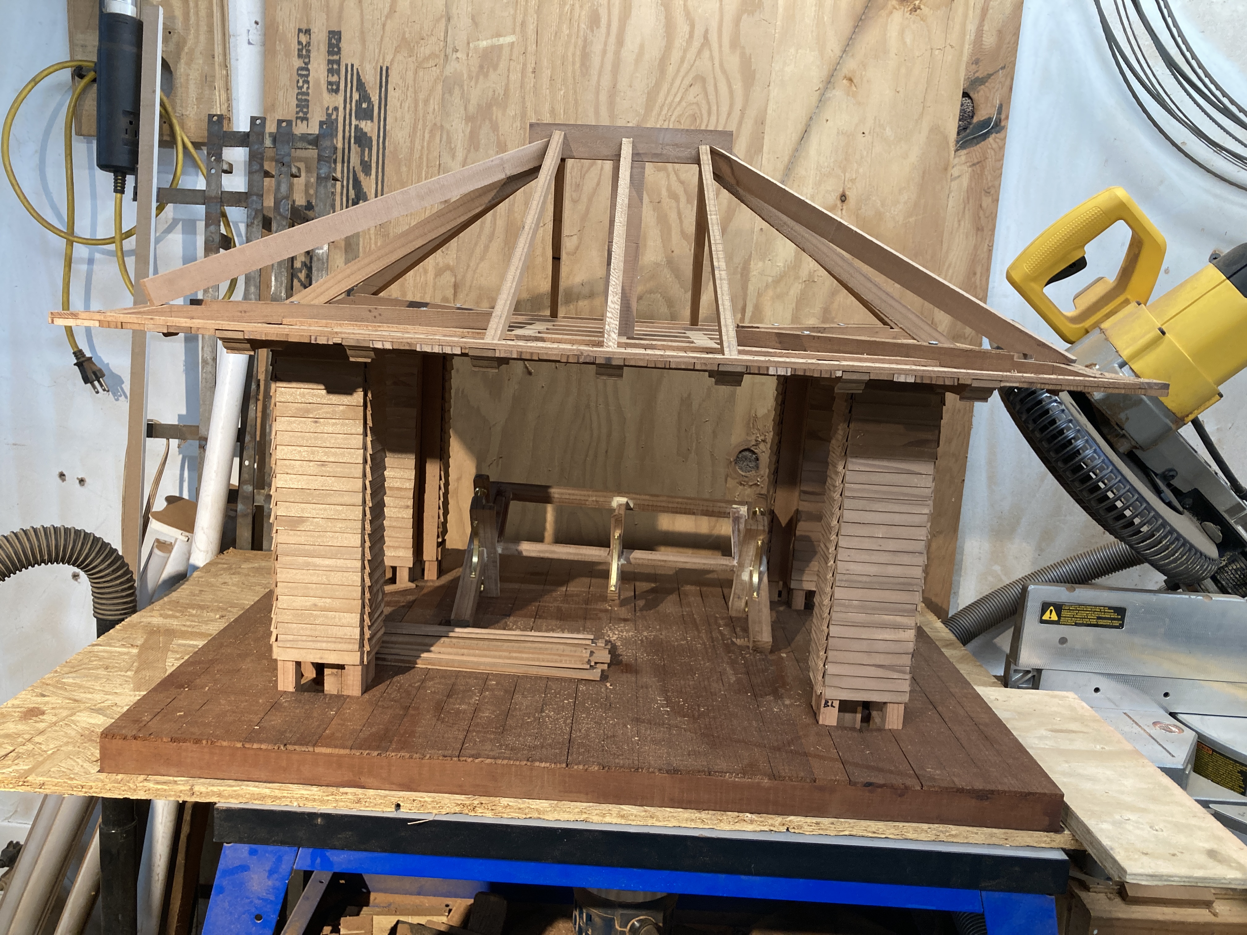
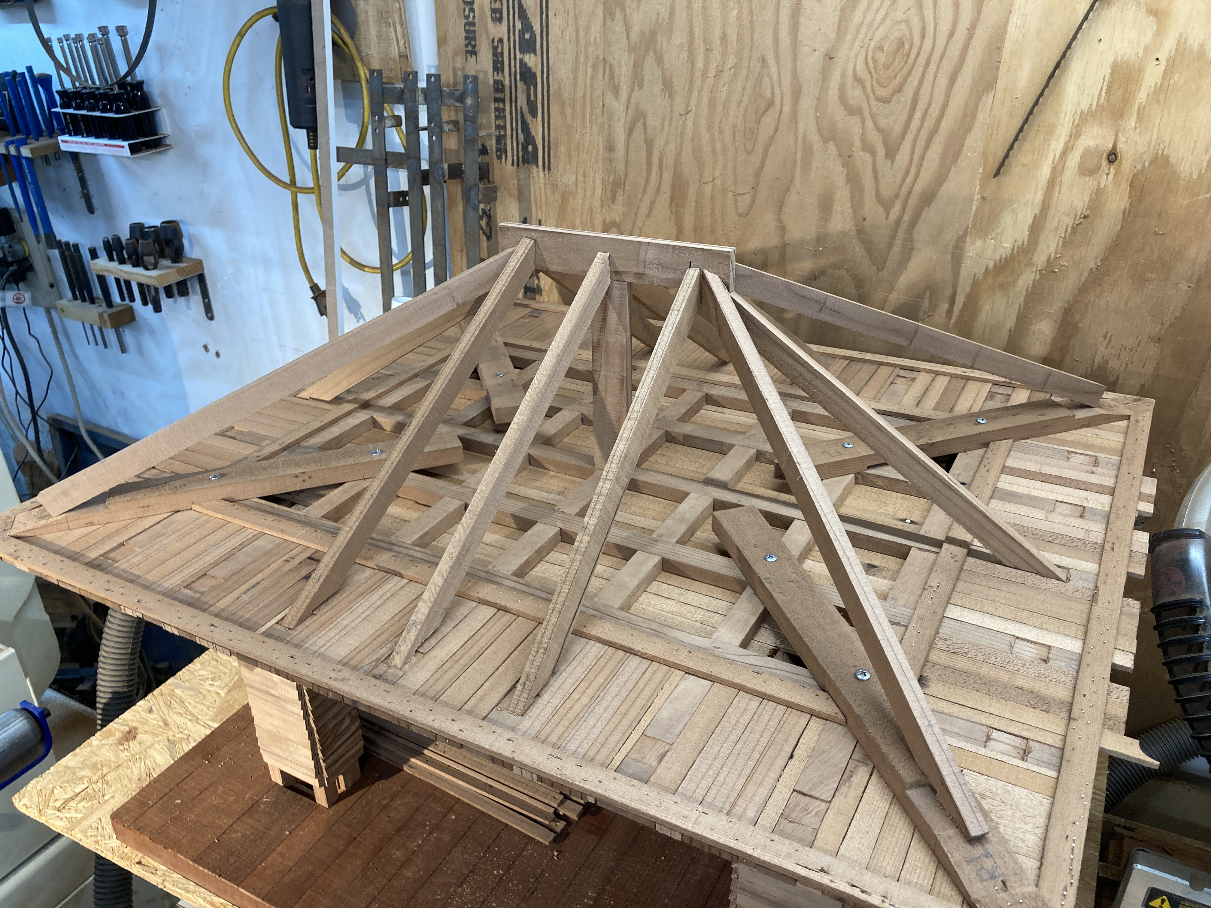
The rafters don't reach the edges as per the prototype. This will create the dual slope roof. The effect is very subtle on the finished building but is very pleasing. I added the four large diagonal beams to support the corners. I'm not sure how such a structure is built in real buildings...
The roof covering was made of three layers: 3mm plywood, weatherproof tape and cedar shingles. Aside from the metal parts, those three are the only parts of the building not made from reclaimed redwood.
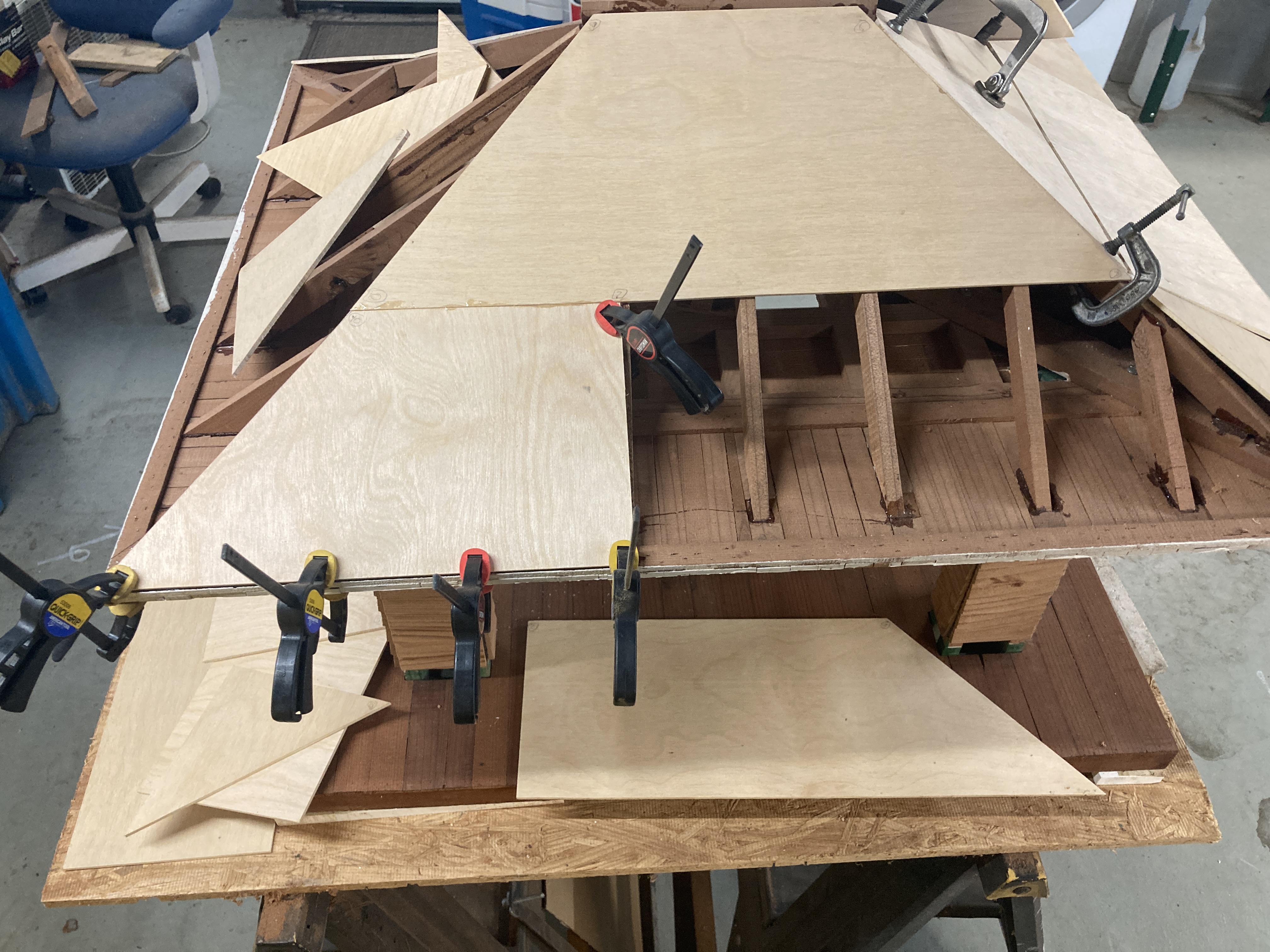
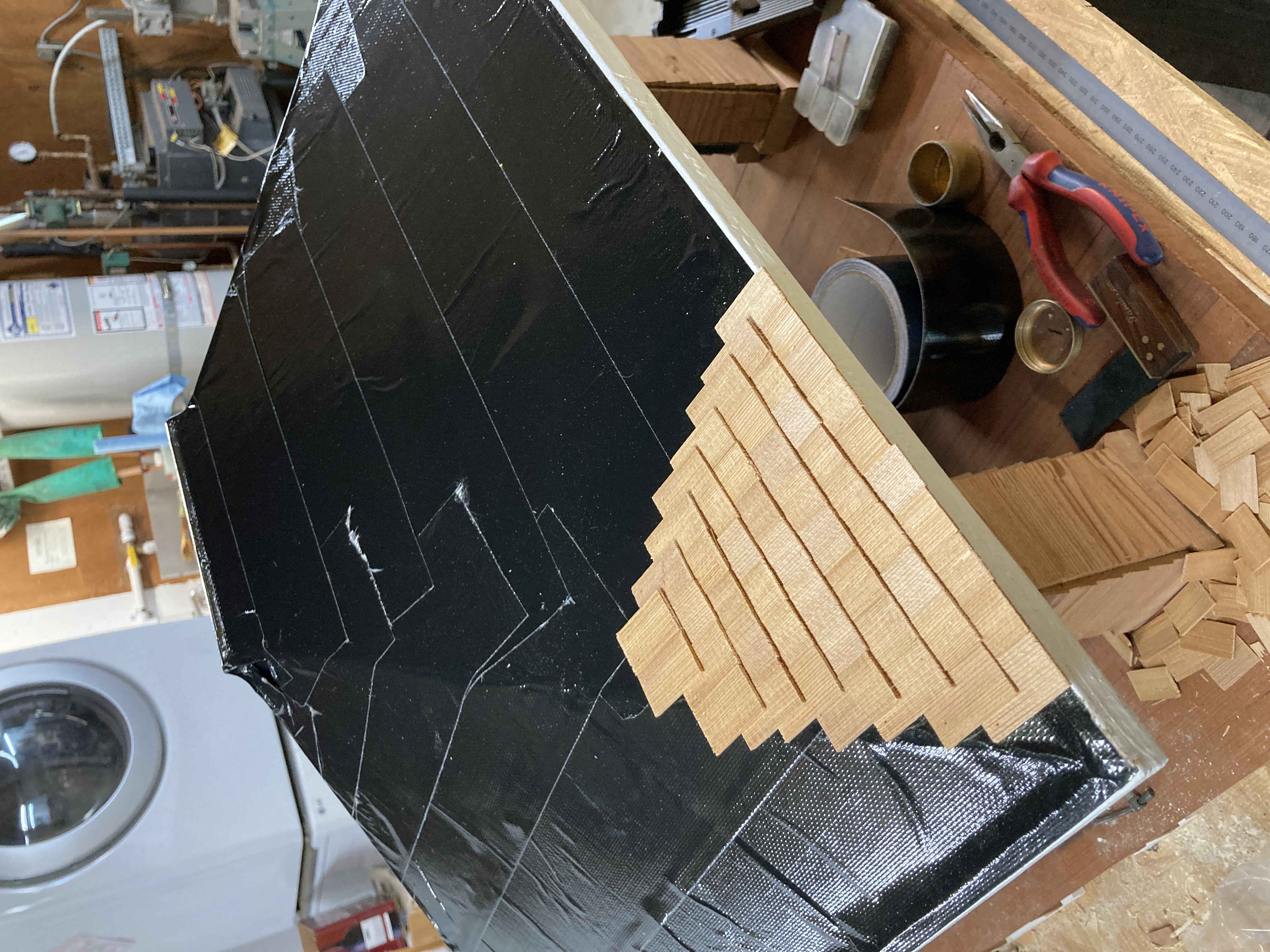
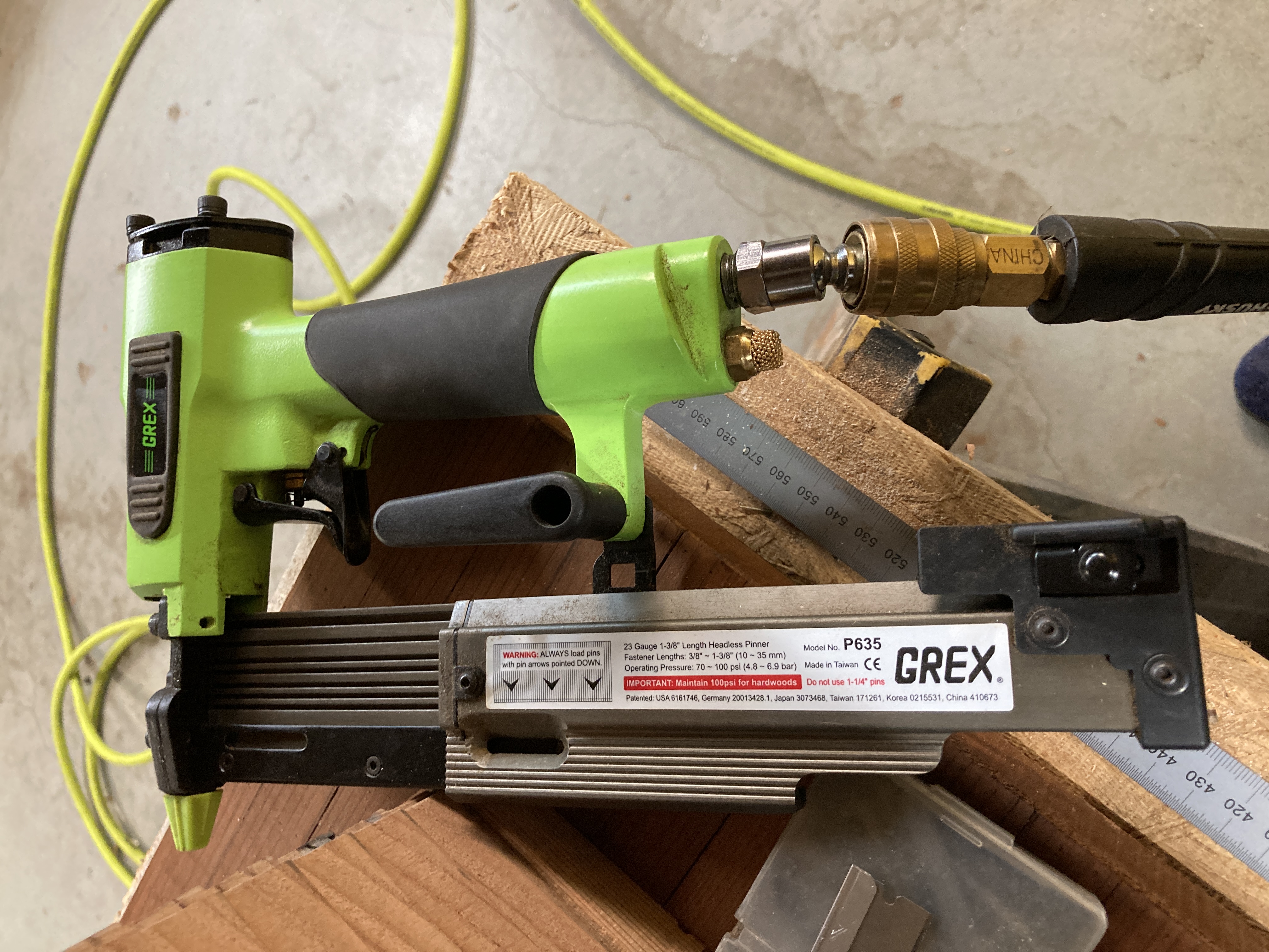
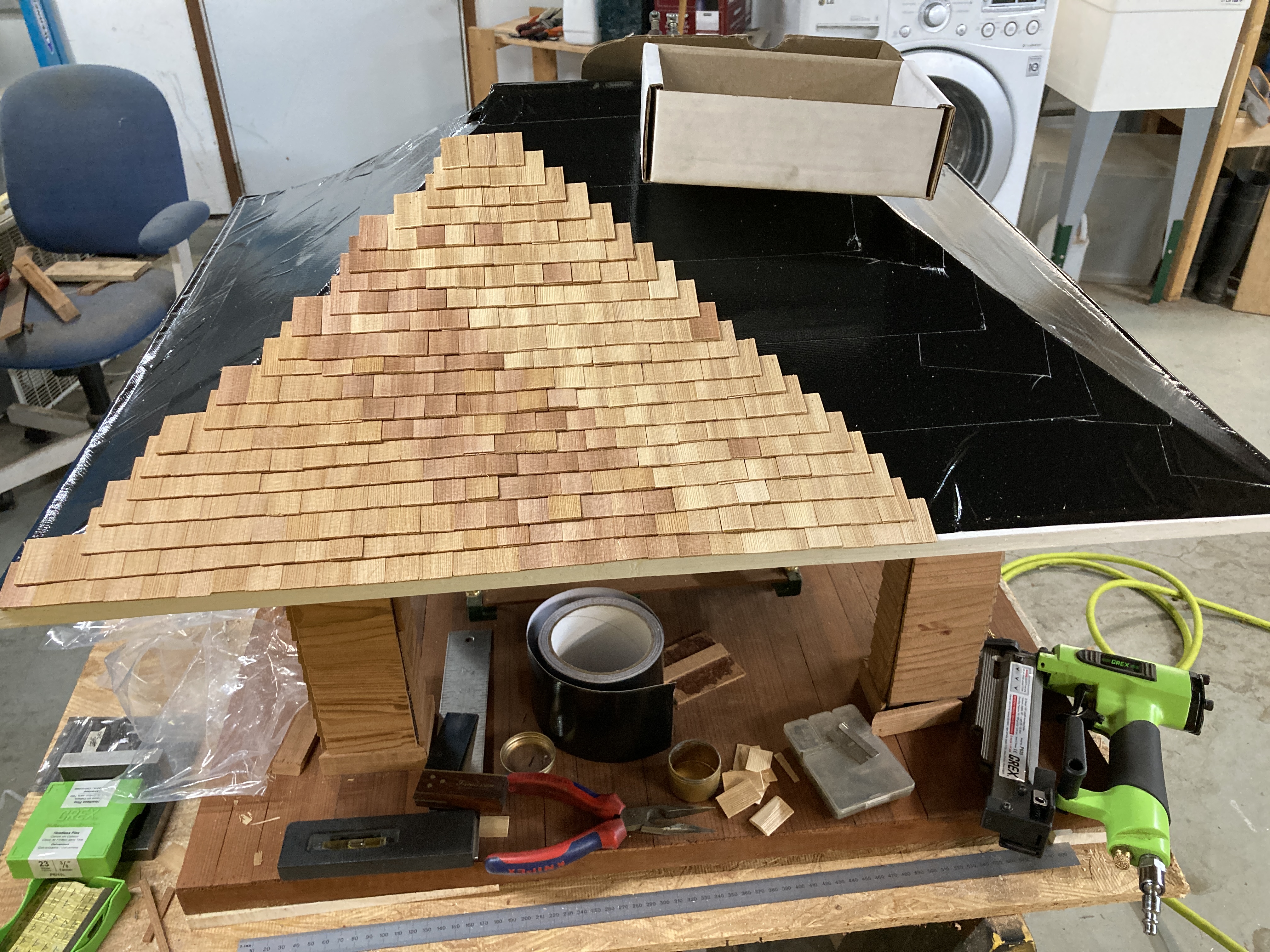
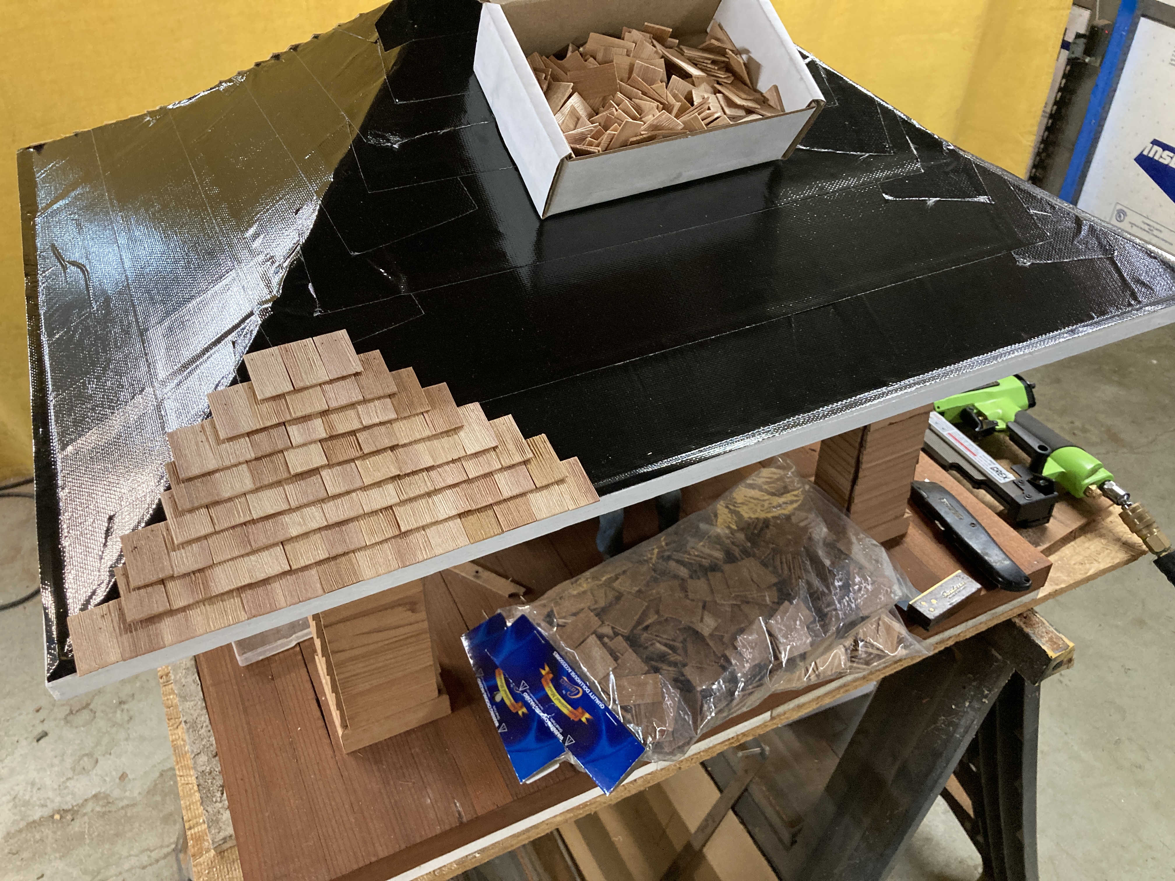
The shingles were nailed into the plywood through the tape. I originally planned to use epoxy in addition to nails but I dicovered that the epoxy does not stick to the tape... I ended up using epoxy to hold the shingles along the four ridges as nailing those was impossible.
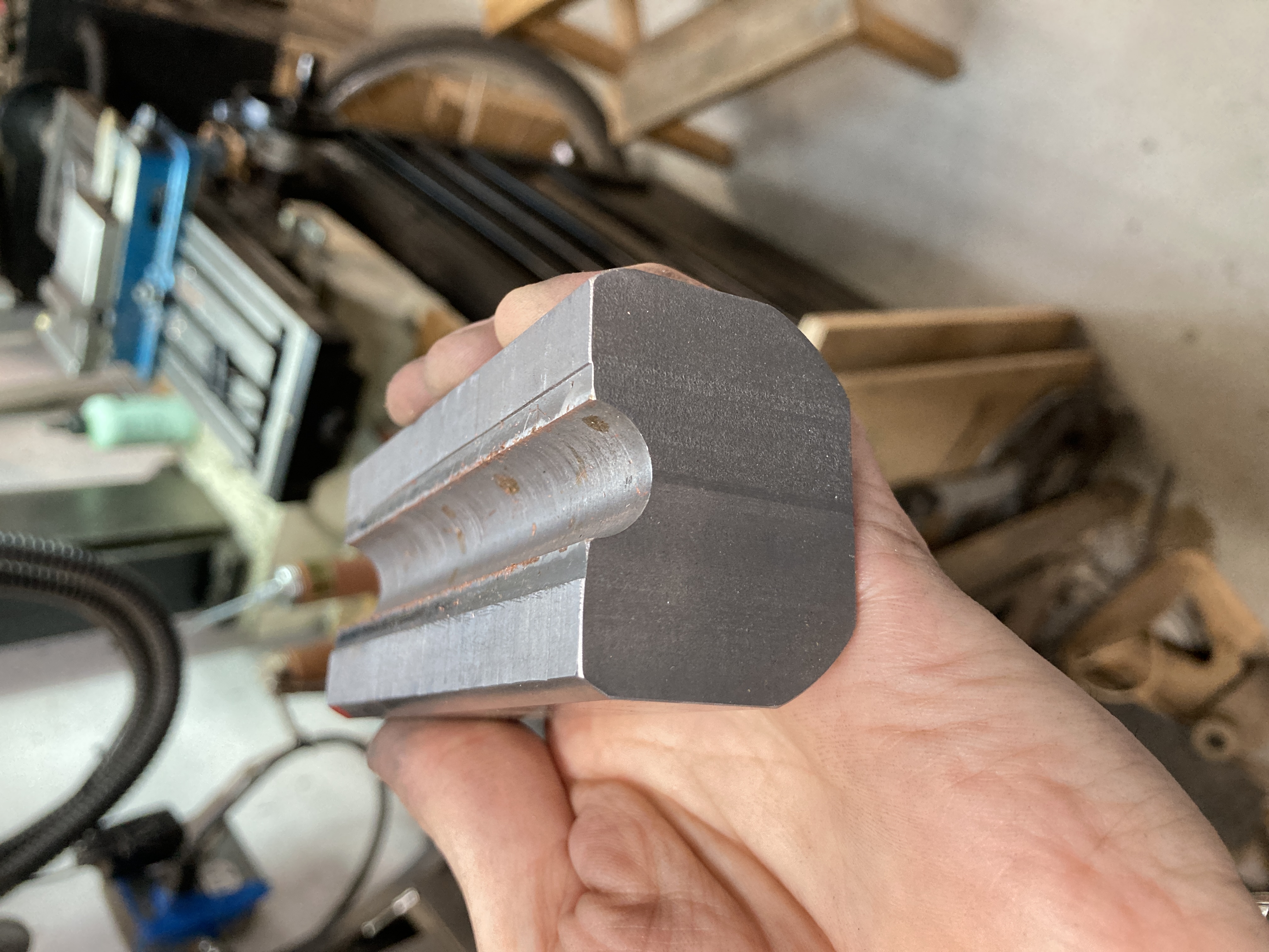
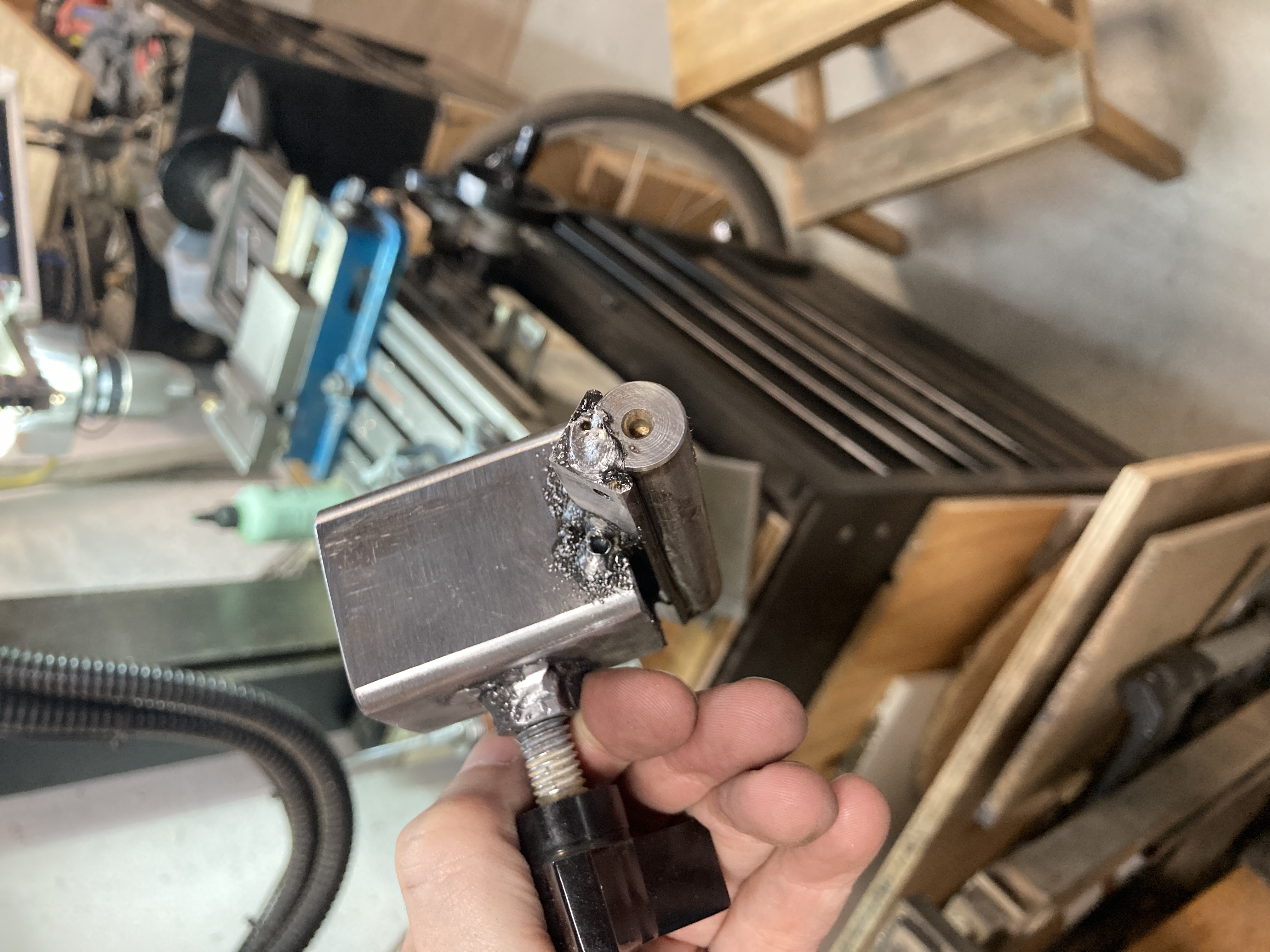
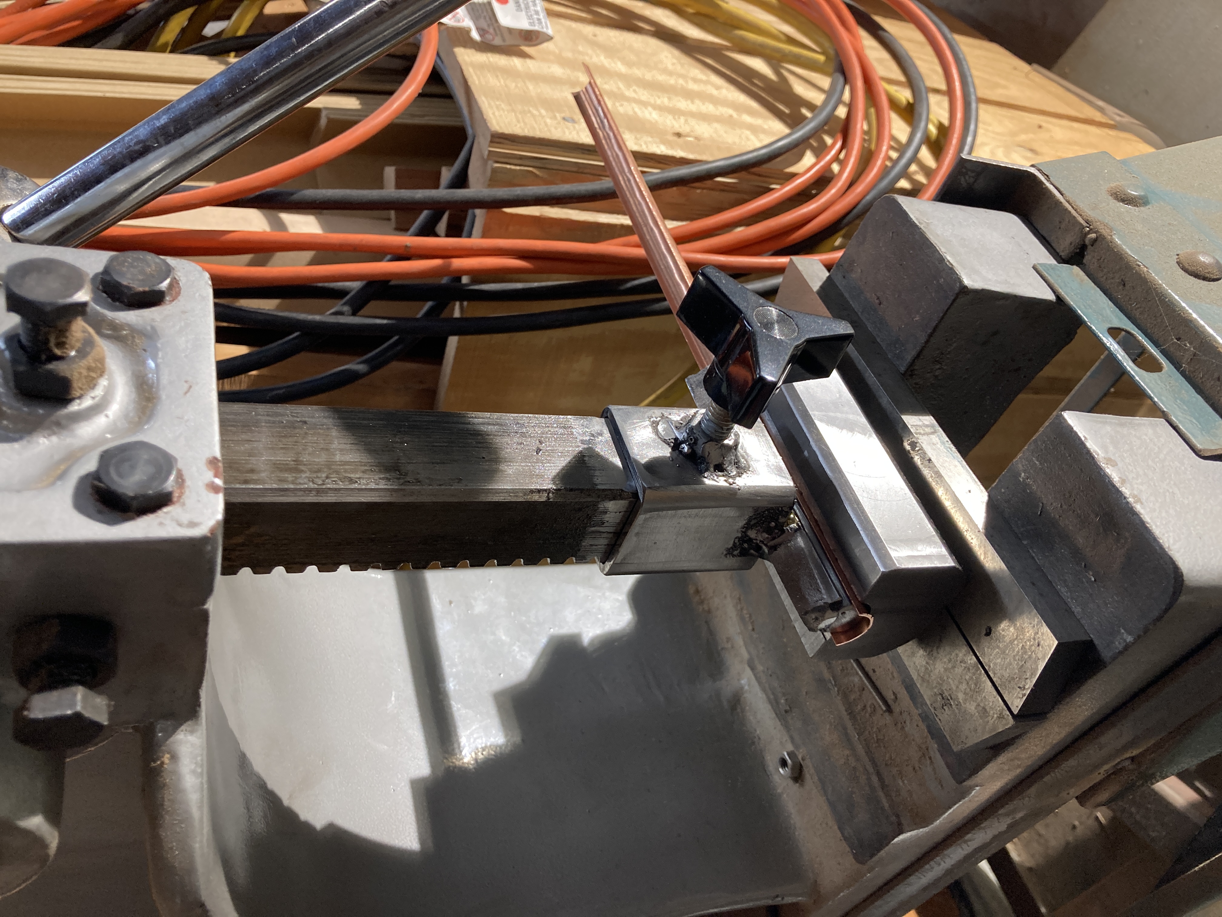
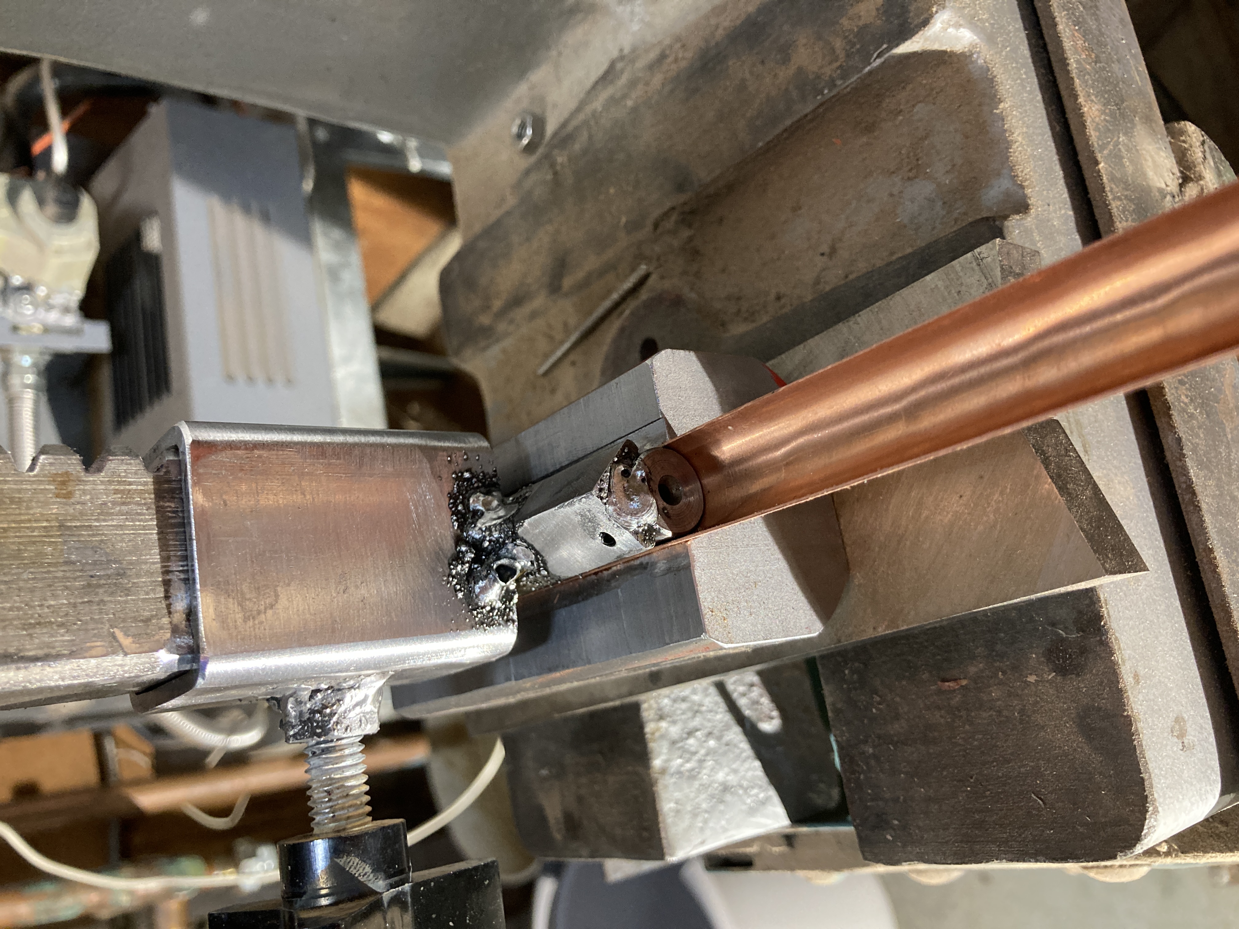
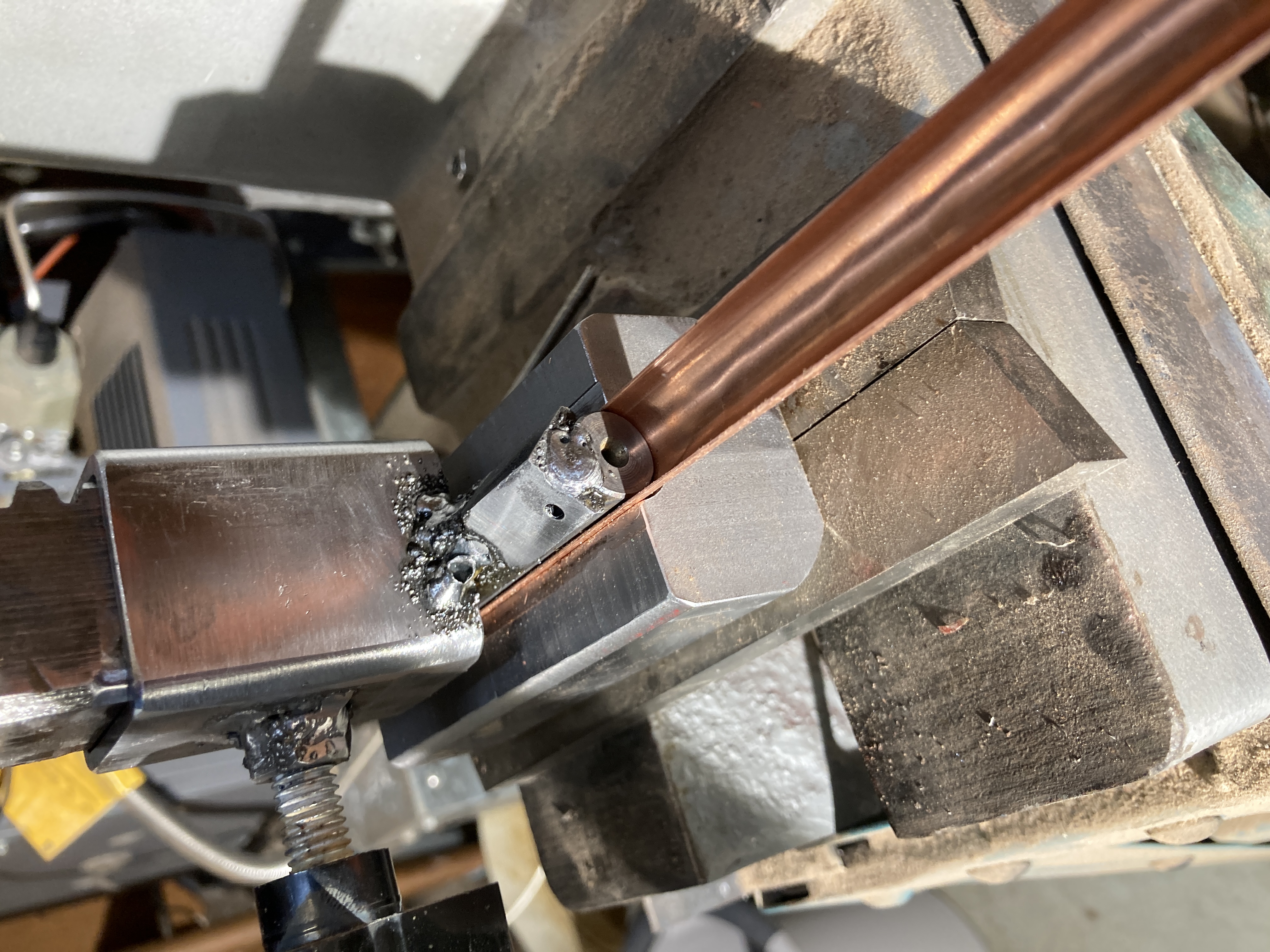
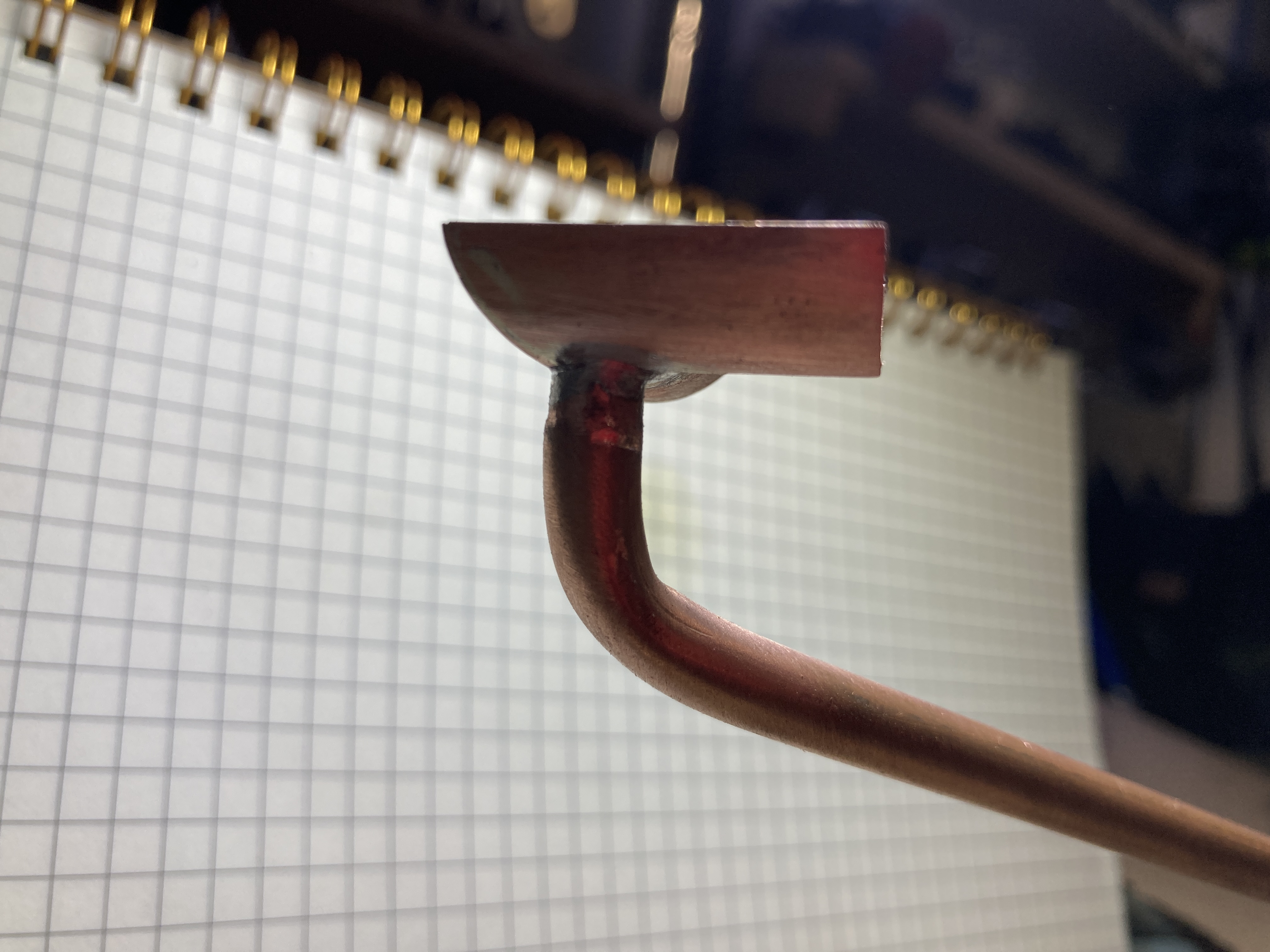
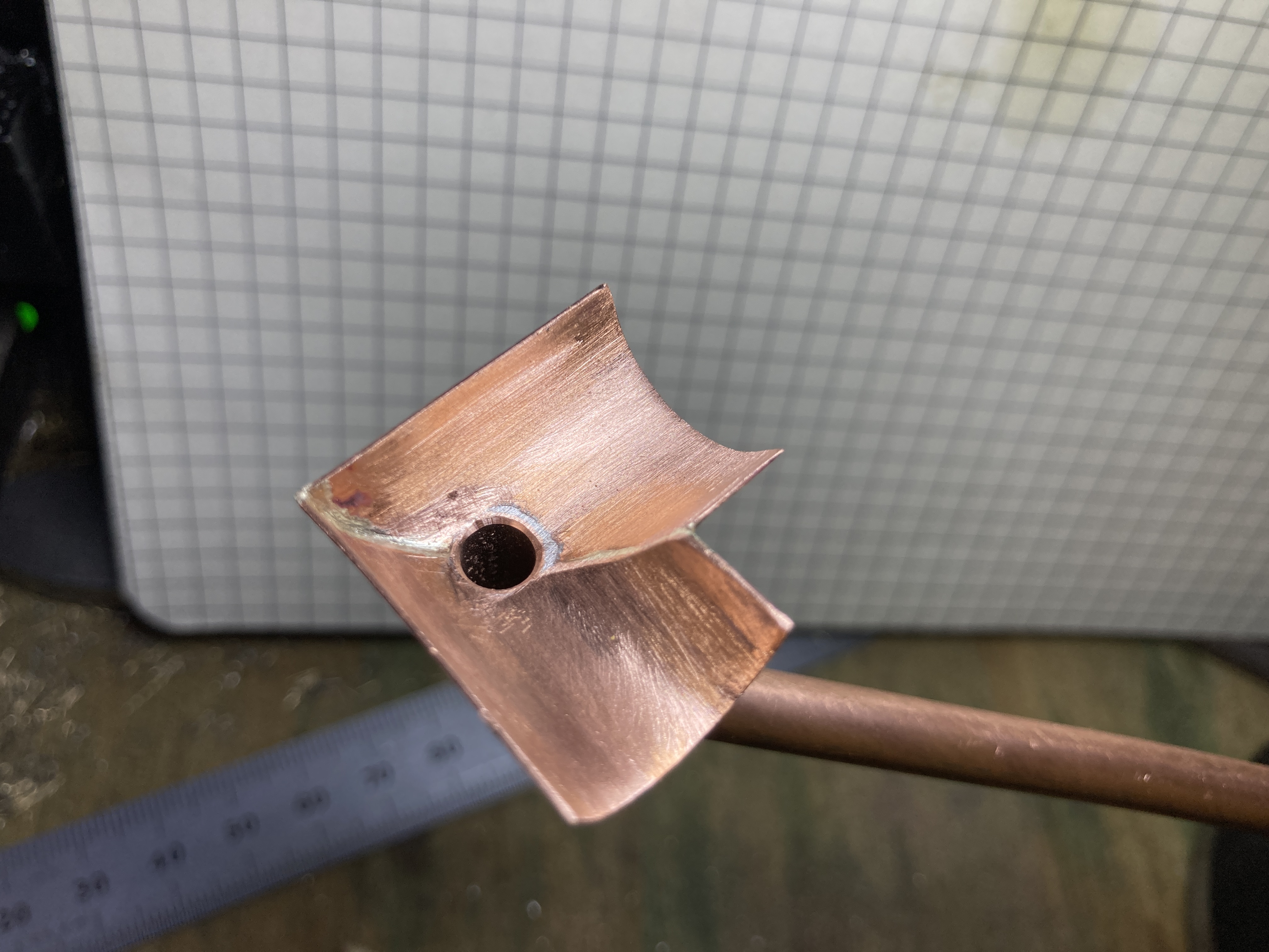
The next step was building the gutters and downspouts. The gutters were made of 0.5mm thick copper. This was a compromise between building a robust model and true scale. Based on the thickness of modern day copper gutters, I should have use metal about 1/2 to 1/3 thinner than I did. To make the gutters, I first considered cutting some copper tubing in half. However, beyond the difficulties of holding the tubing during the cut, I realized that even the thinnest tube I could find had much too thick walls. So I bought some flat sheet and built a tool for my press to form it into gutters.
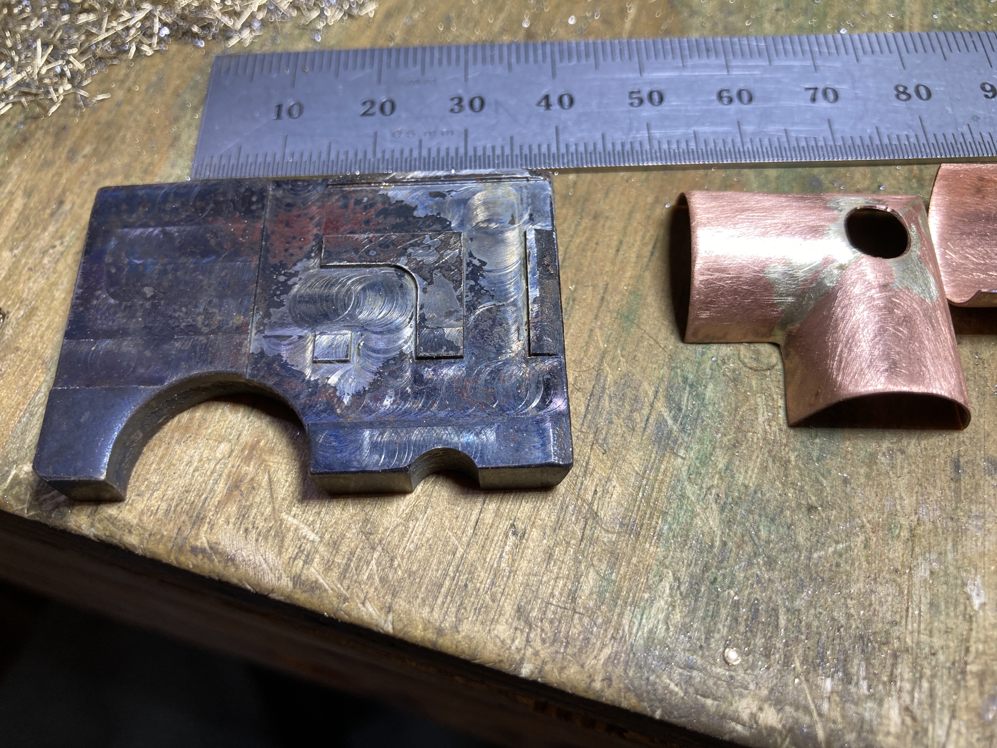
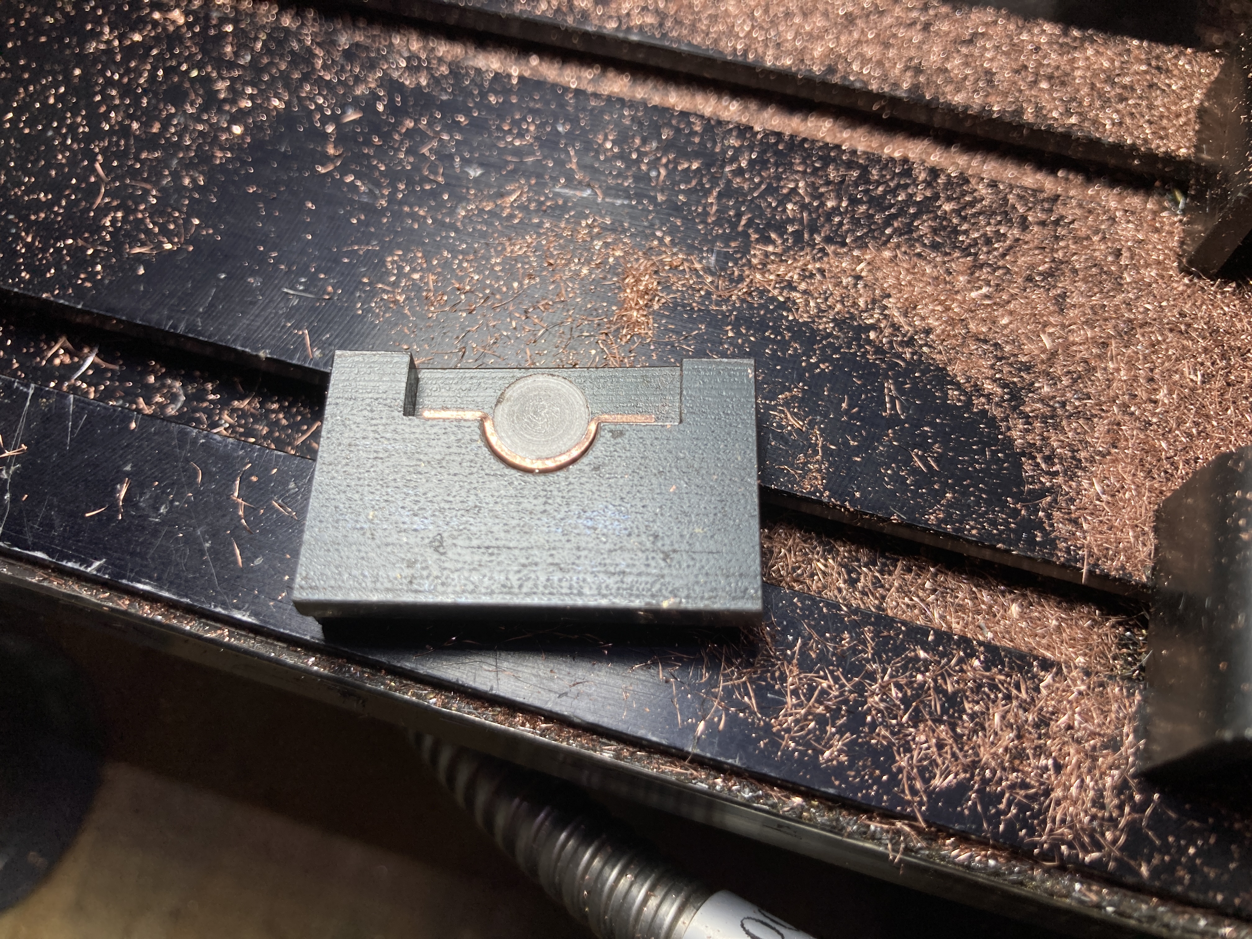
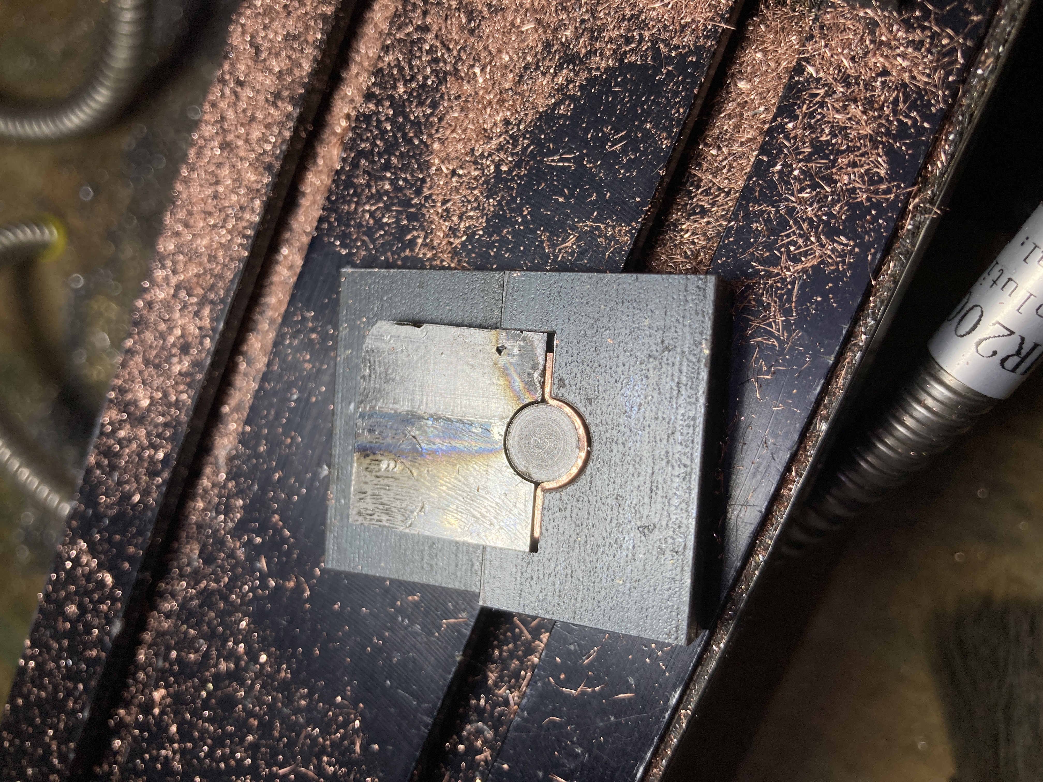
The corners were made by silver soldering two short pieces of gutters that were cut with a mitter. In order to hold the parts during soldering, I made a fixture out of a steel plate in which I machined a recess.
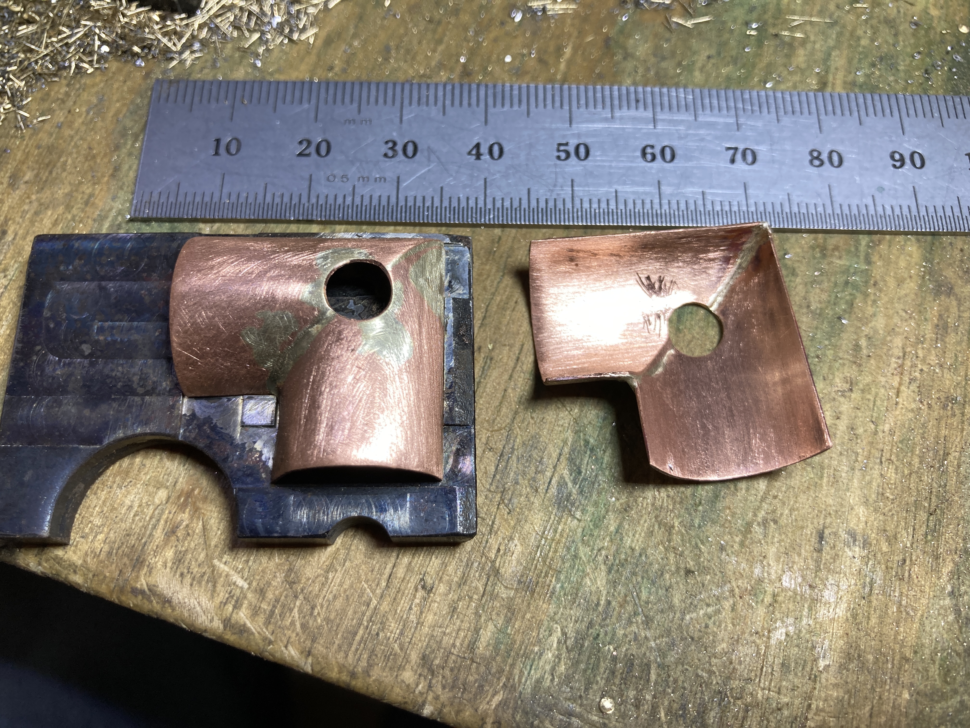
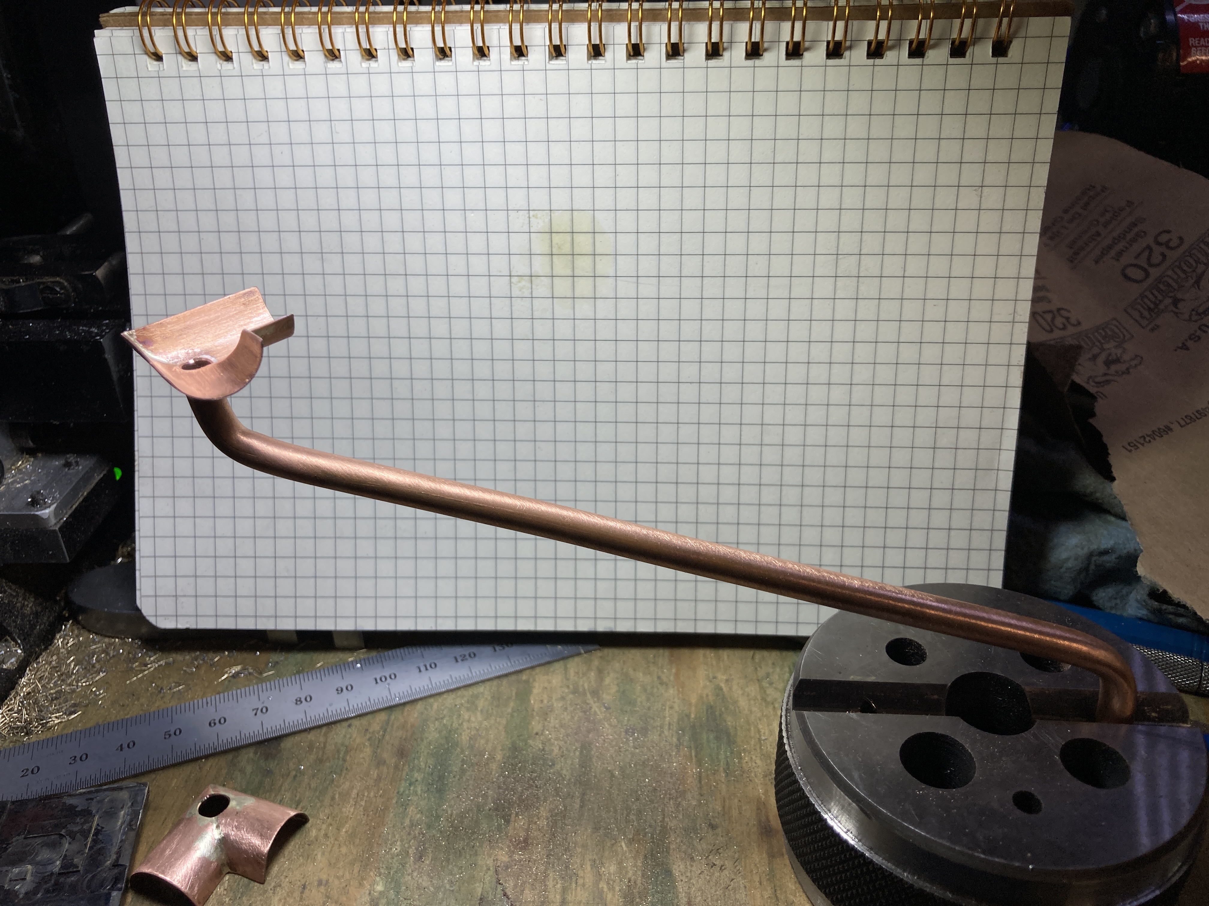
I used silver solder to put the two halves together because further assembly would be done with low temprerature solder (like the kind used by plumbers). The upper sections of the downspouts were attached next.
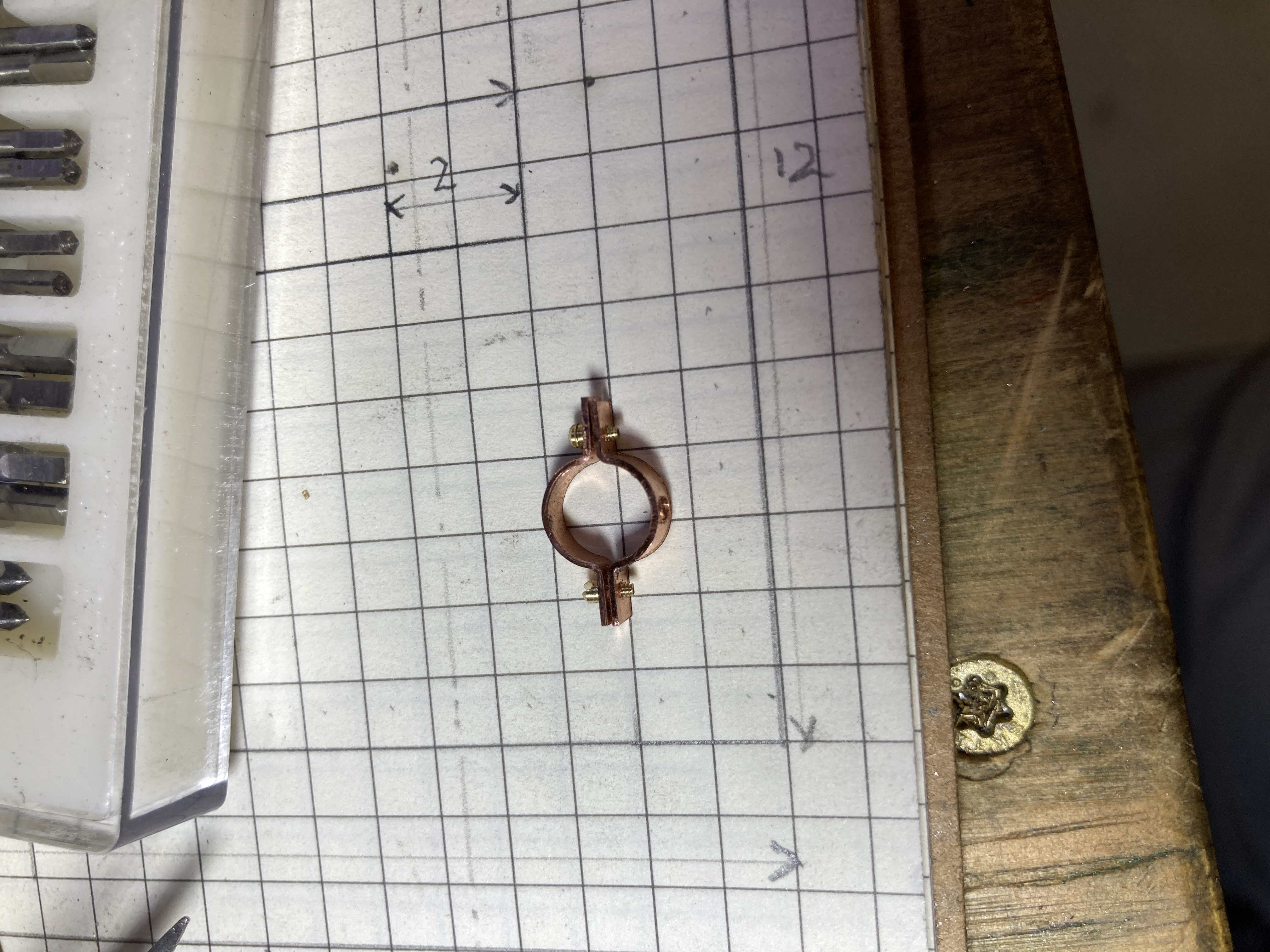
To hold the vertical part of the downsputs to the columns, I decided to build some as-close-to-scale-as-possible brackets. This involved shaping and drilling copper strips by using another fixture.
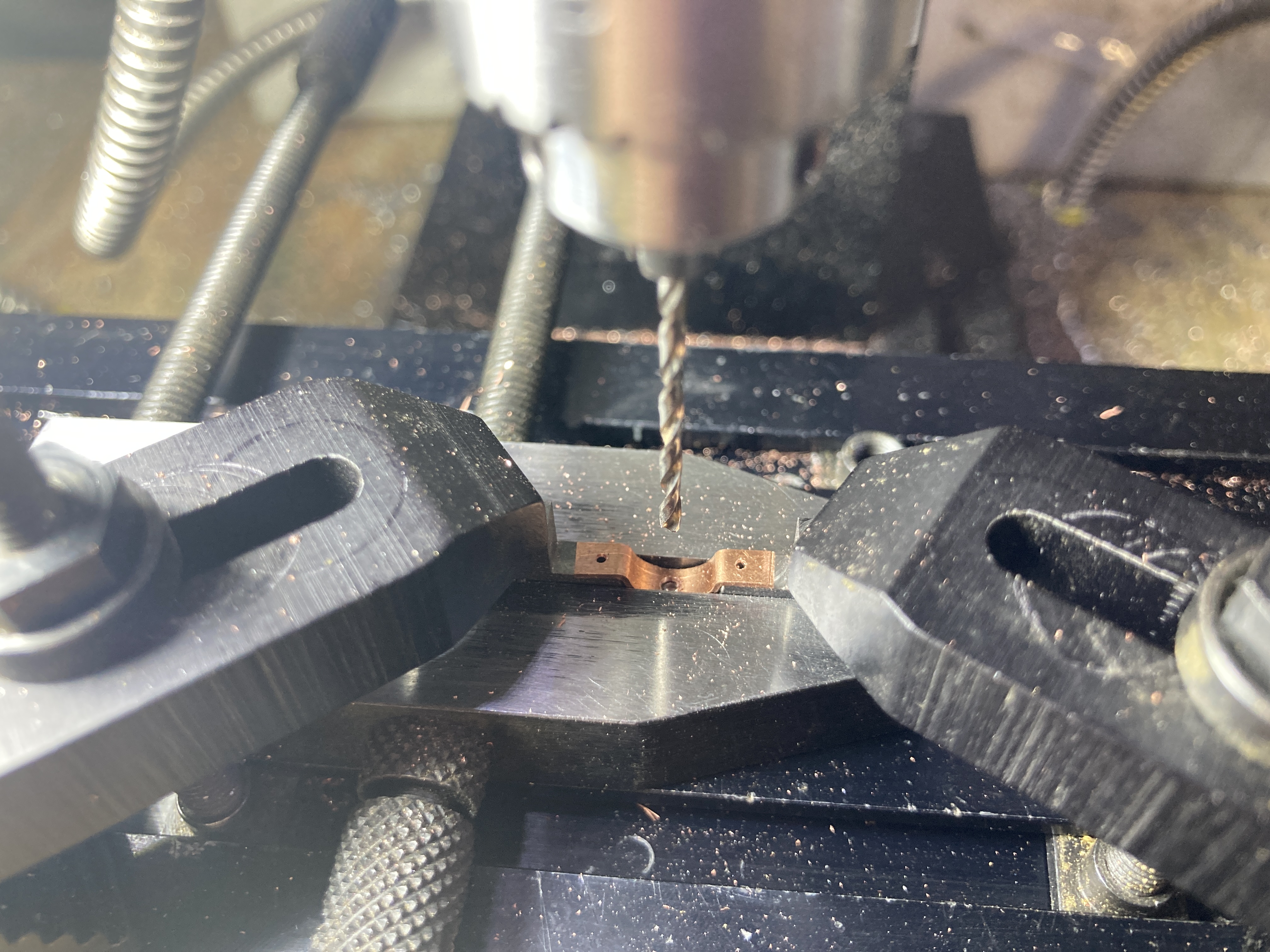
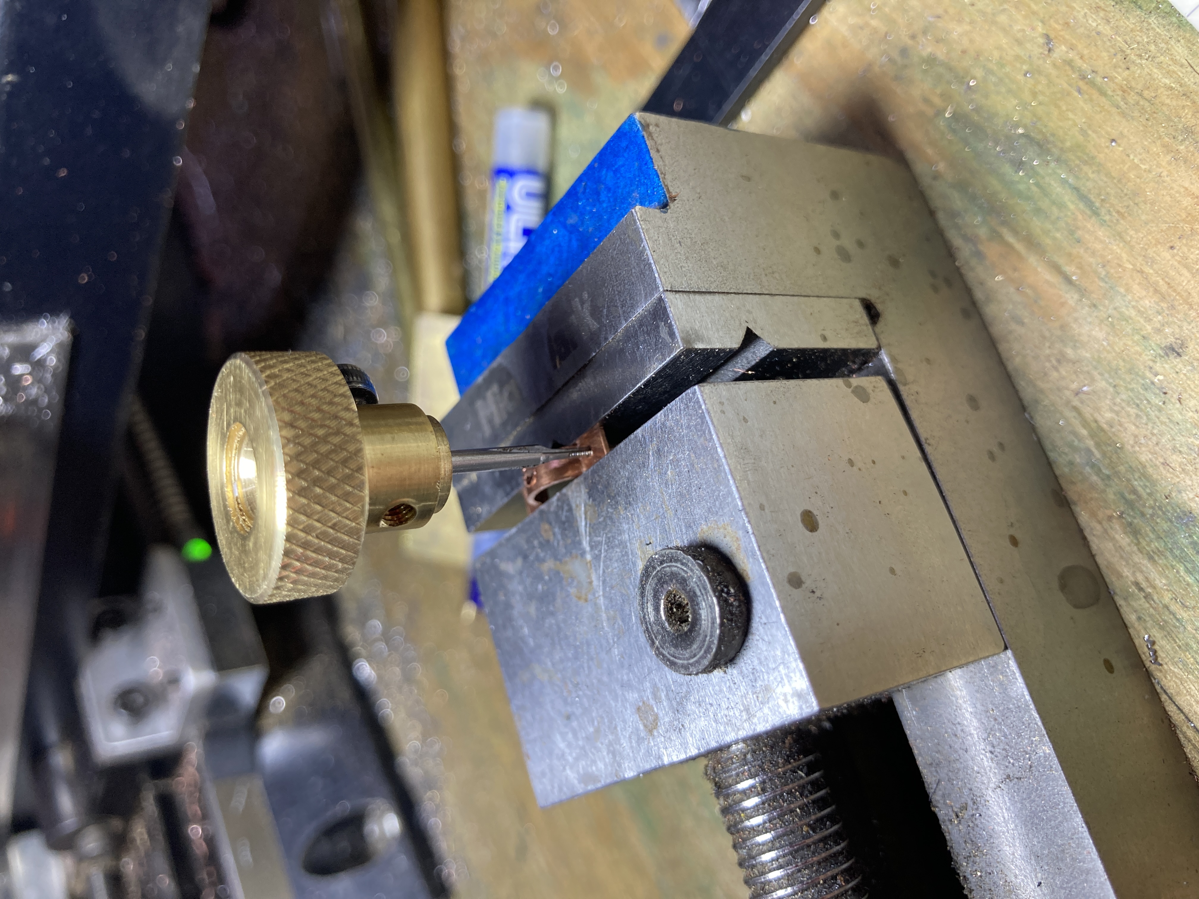
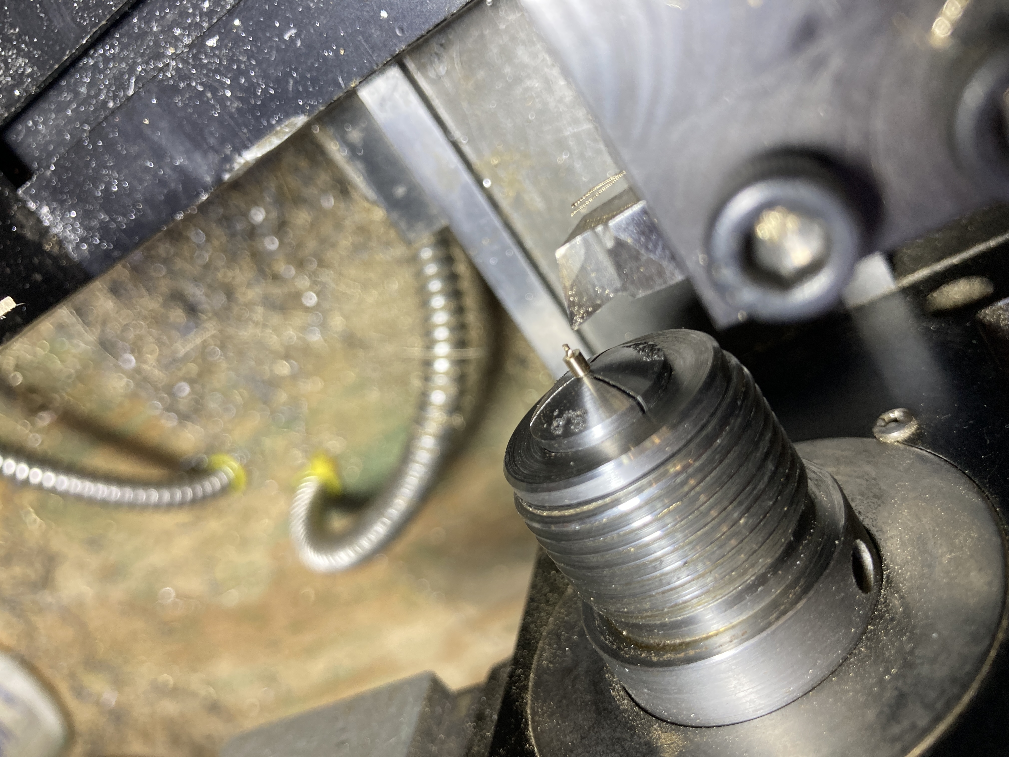
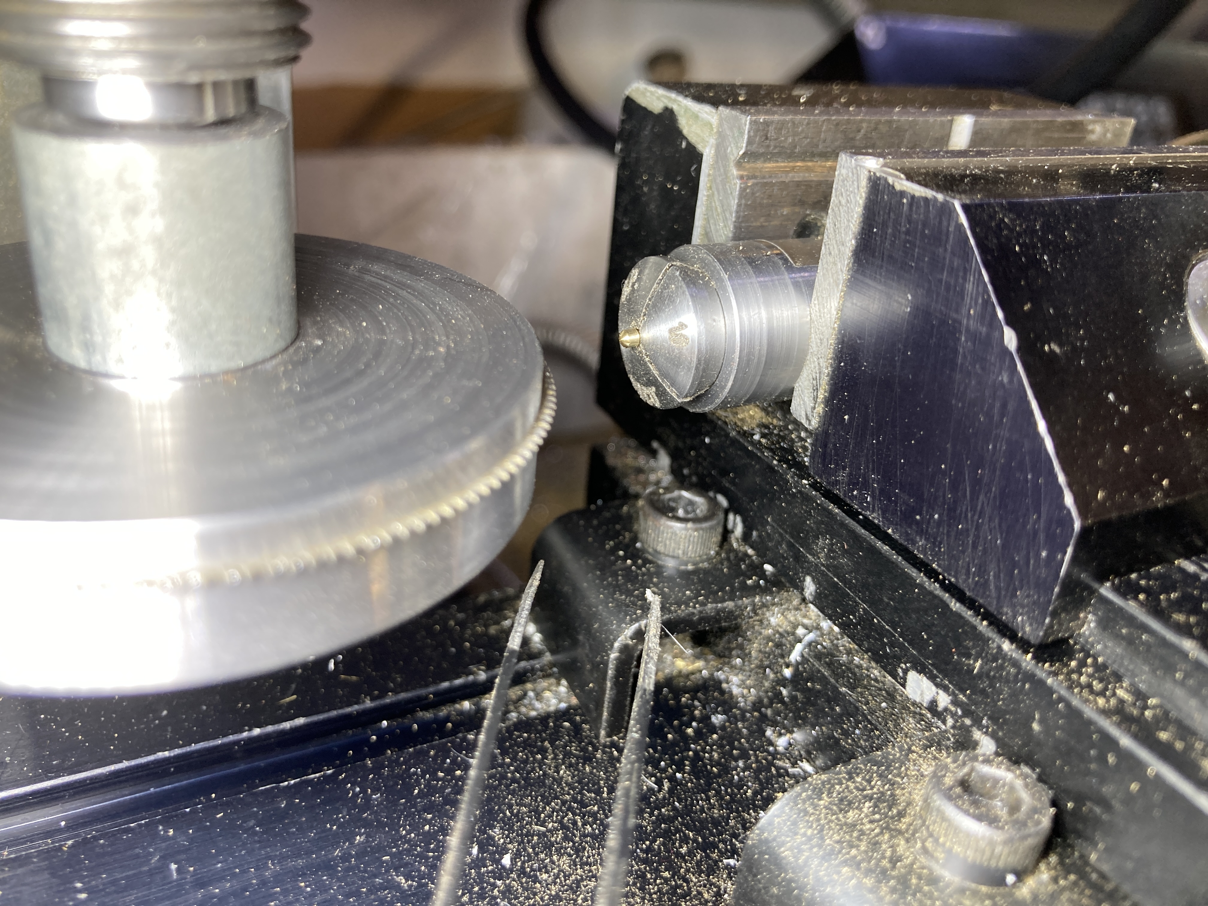
That last picture shows one of the holes being tapped M1x0.2. I also made the matching screws which involved a lot of "side projects": I made a holder for an M1 die, a collet block that accepts ww collets, an adpter to mount those same collets into the ER16 spindle of my lathe and a precision holder for a sliting saw. The later fast first used to hold a 0.5 mm thick saw while I used a carbide end mill to machine it down to 0.3 mm thickness as the screw heads were only 1.5 mm diameter and a 0.5 mm slot through them would weaken them too much.
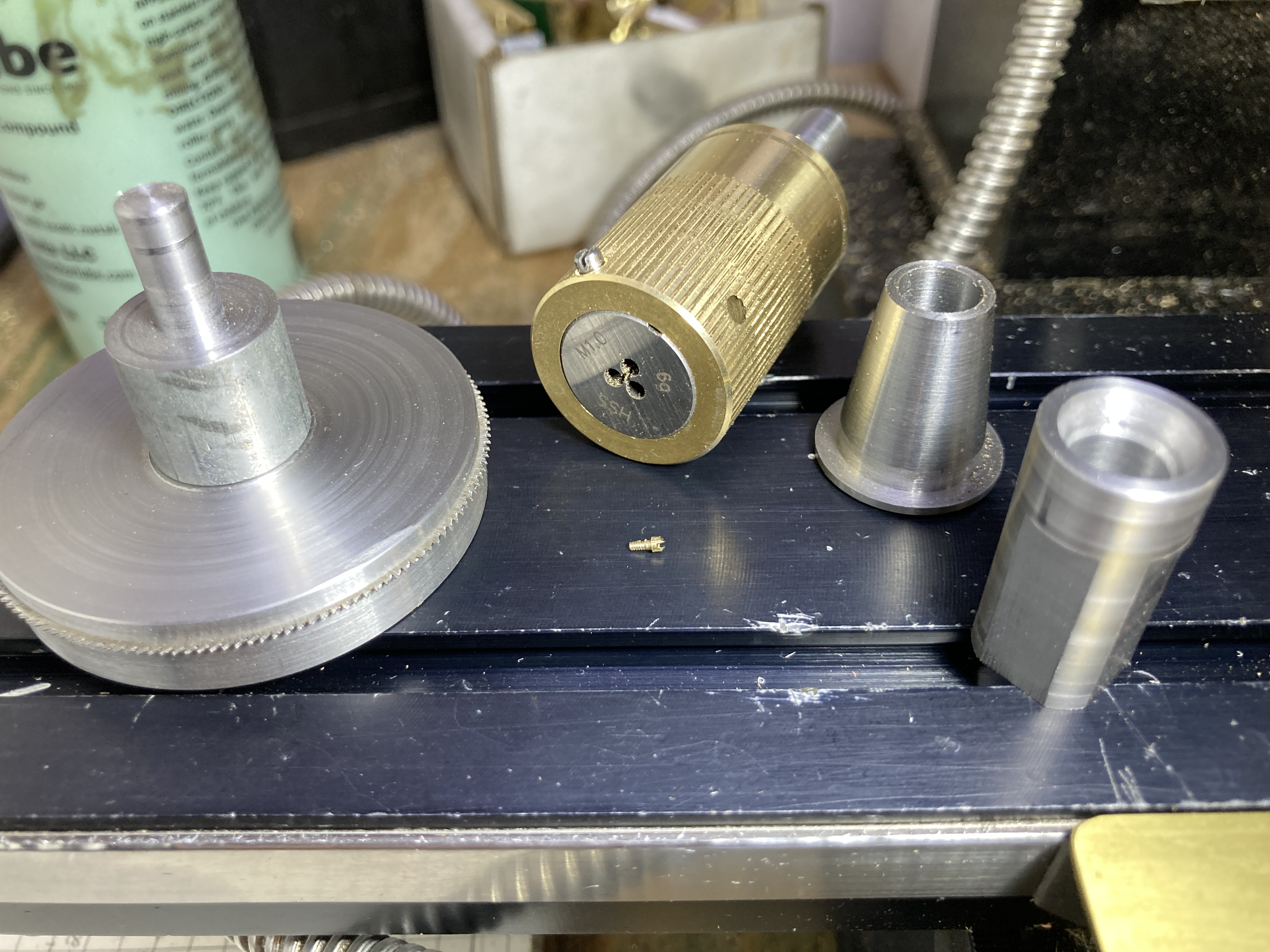
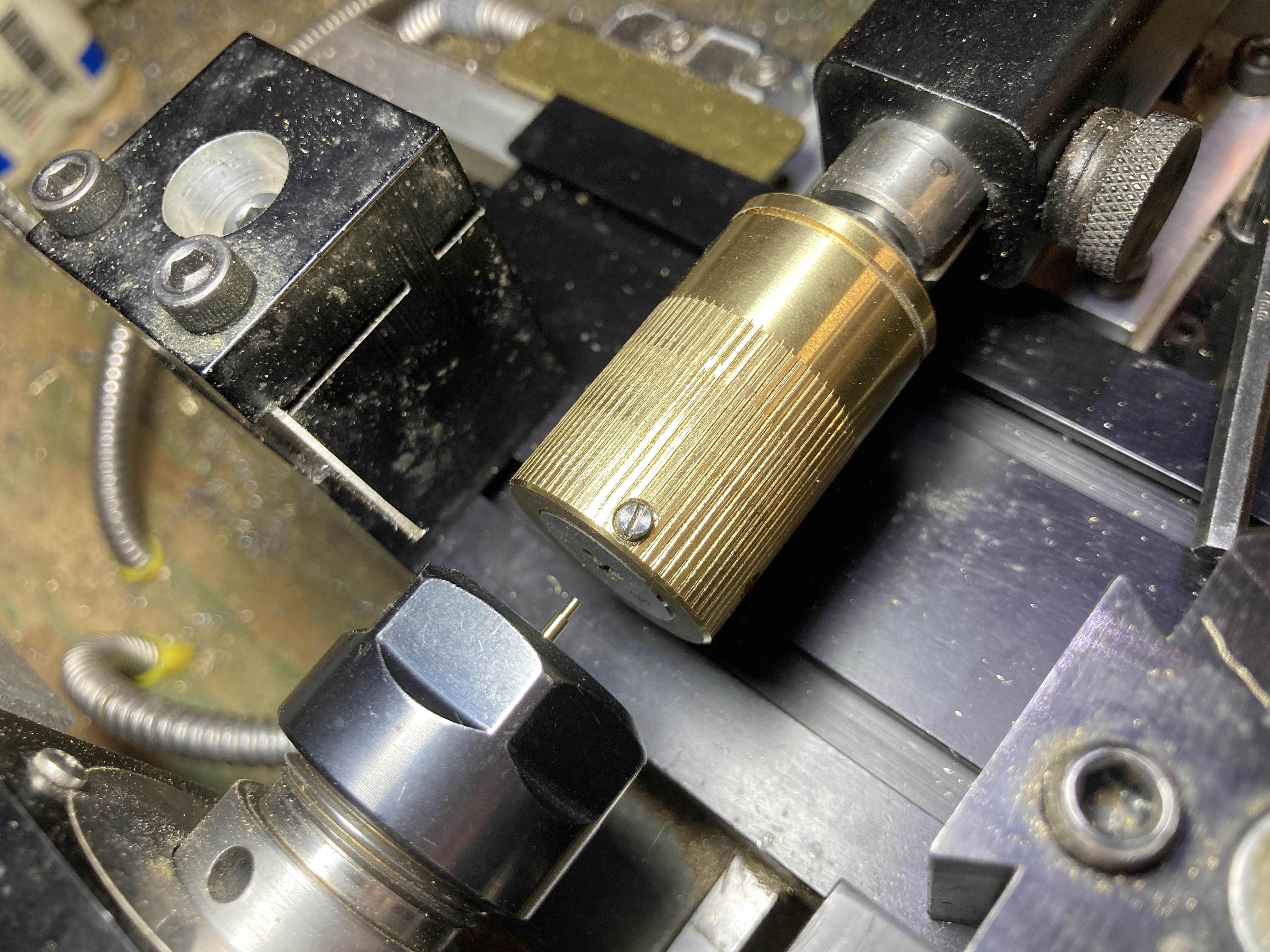
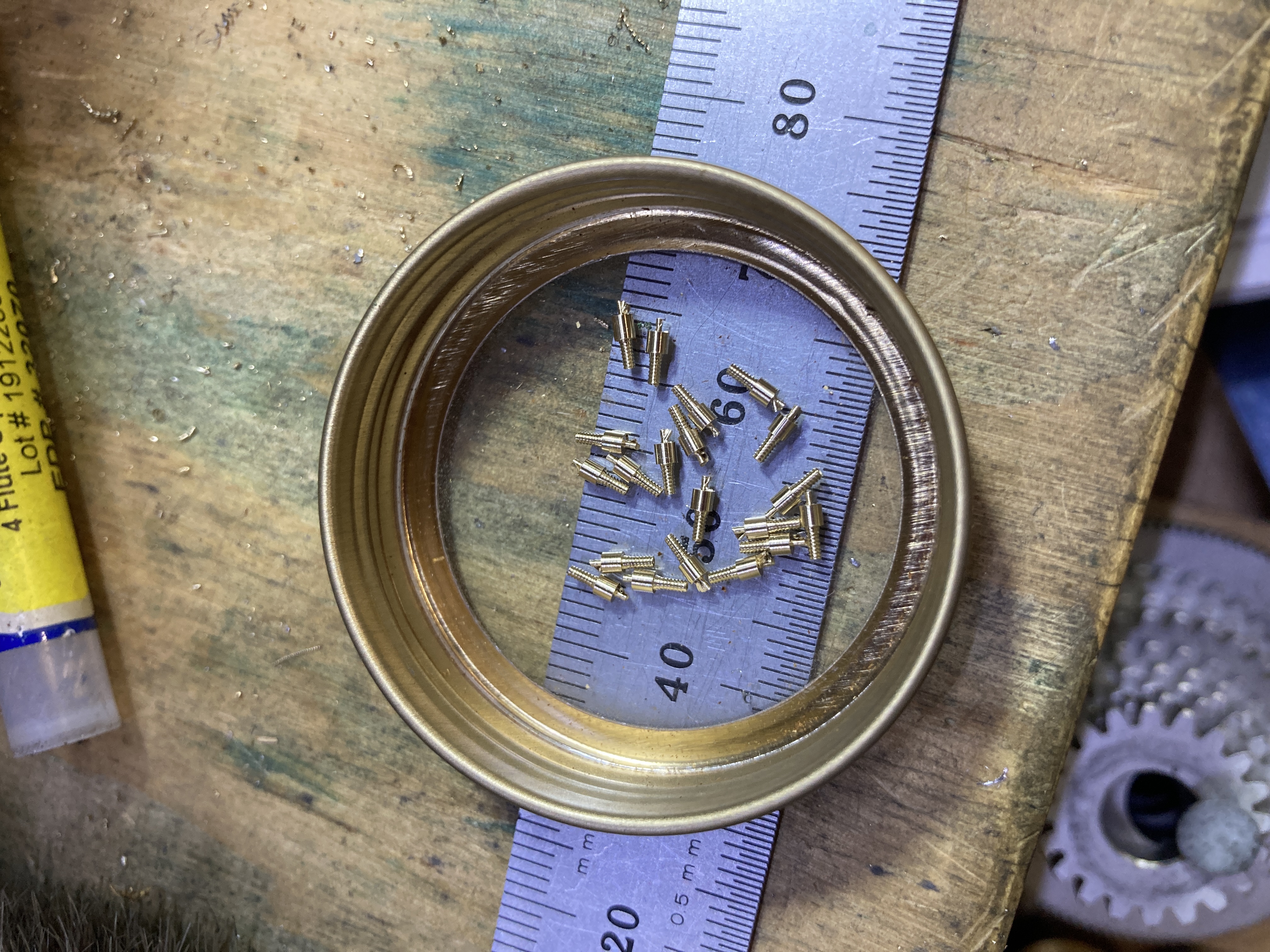
I made 24 screws (and did not lose any, despite several falling on the floor!). Starting with 3mm brass rod, I turned a 1.5mm diameter head and a 1mm diameter body. The body was then threaded with a die. After parting, the screw was held in a 1mm collet by its threads and the top of the head was rounded using the radius cutting attachement. Finally, the screw was transferred on the mill to cut the slot in it head.
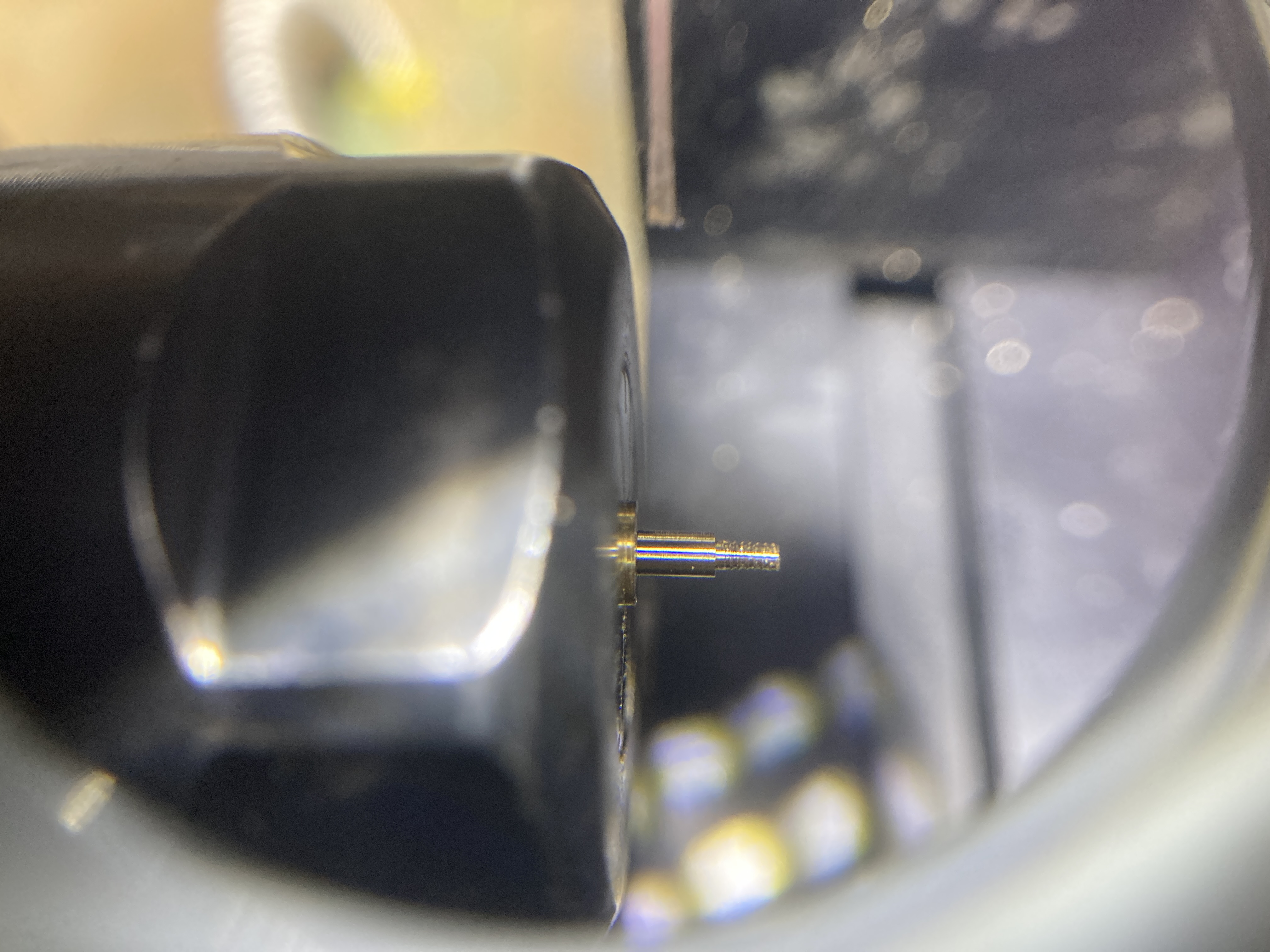
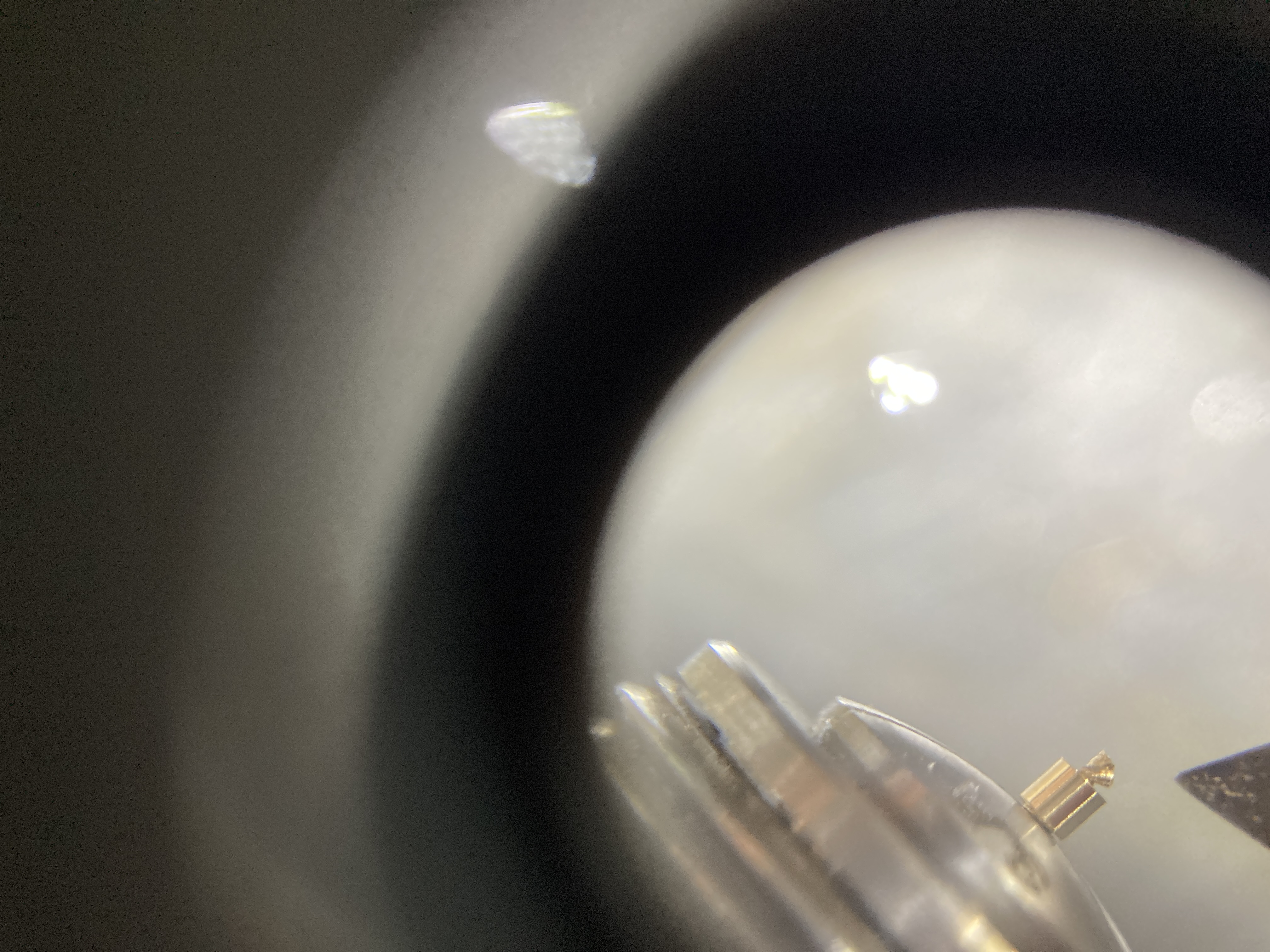
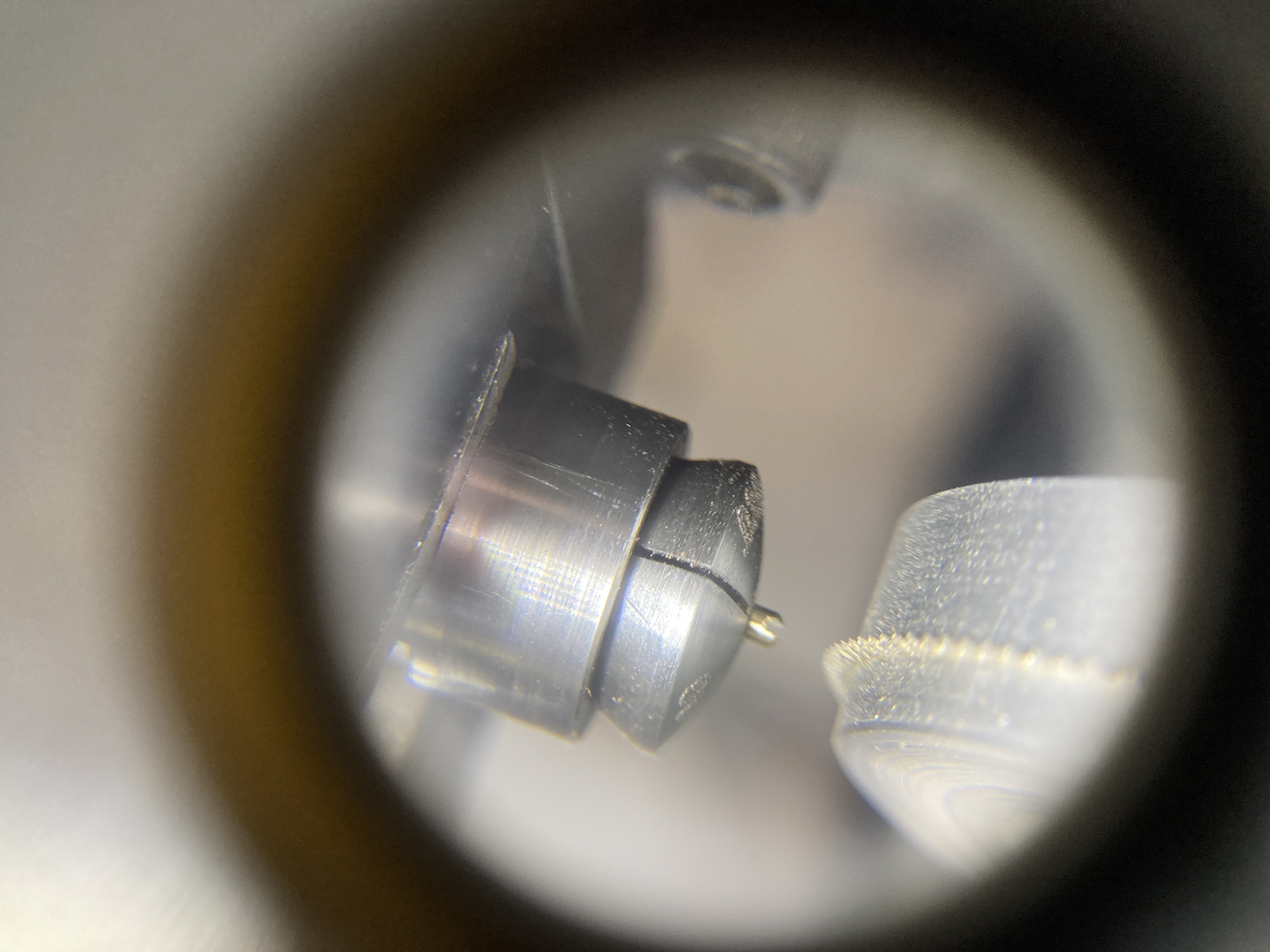
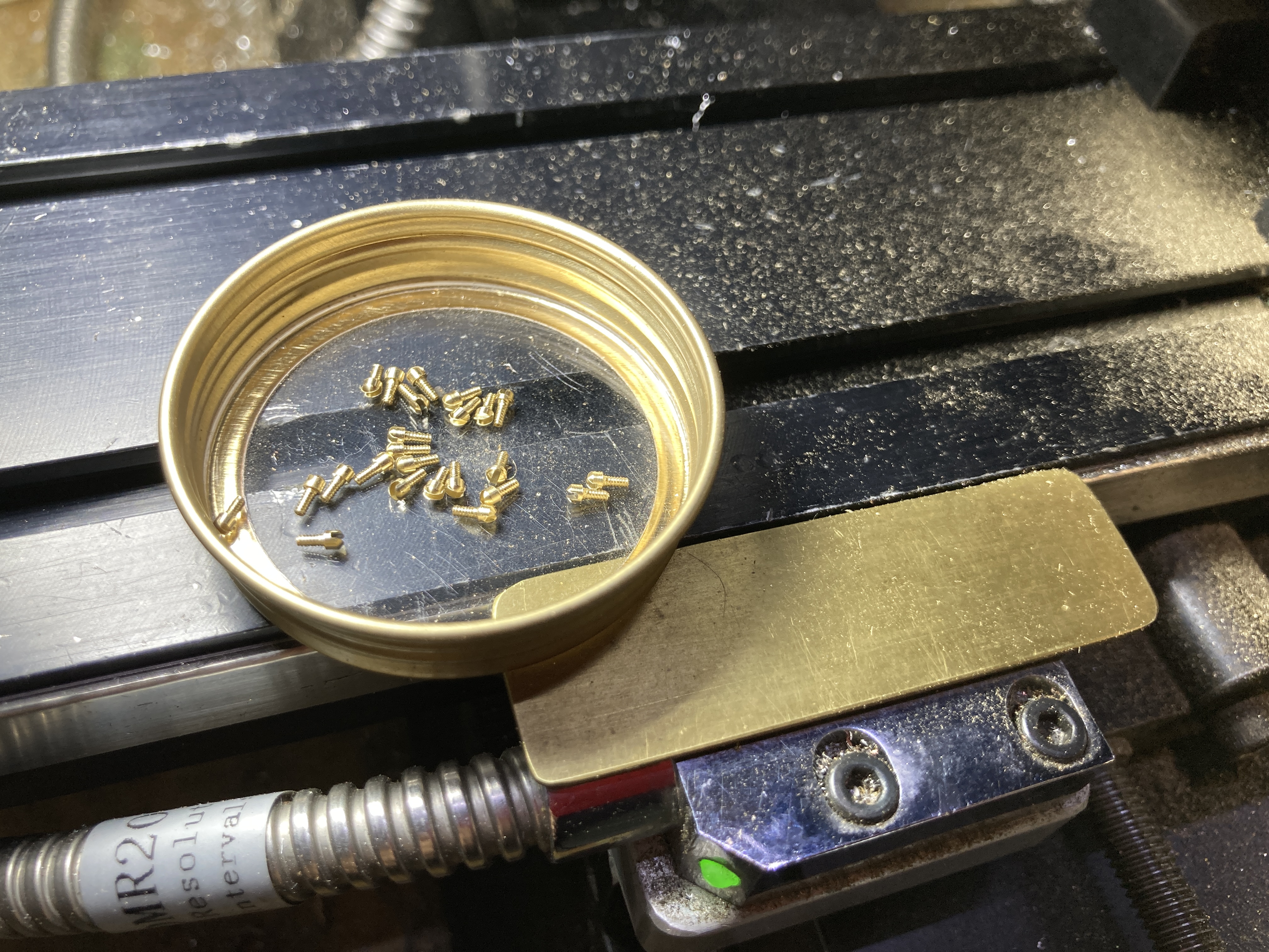
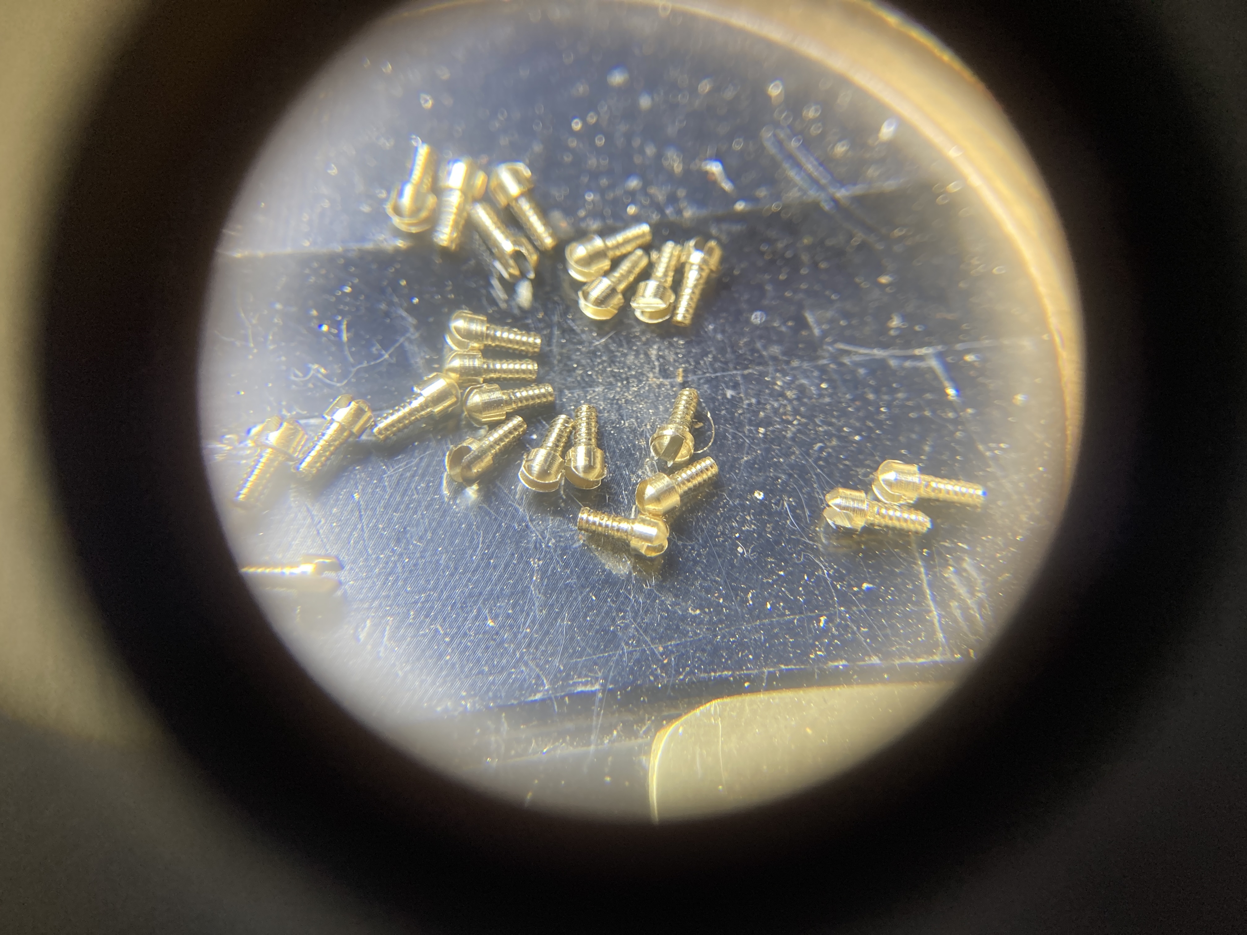
Some of the closeup phots were taken by putting my phone camera on top of a 6X jeweler's loupe. The result of all this work is shown in the next picture.
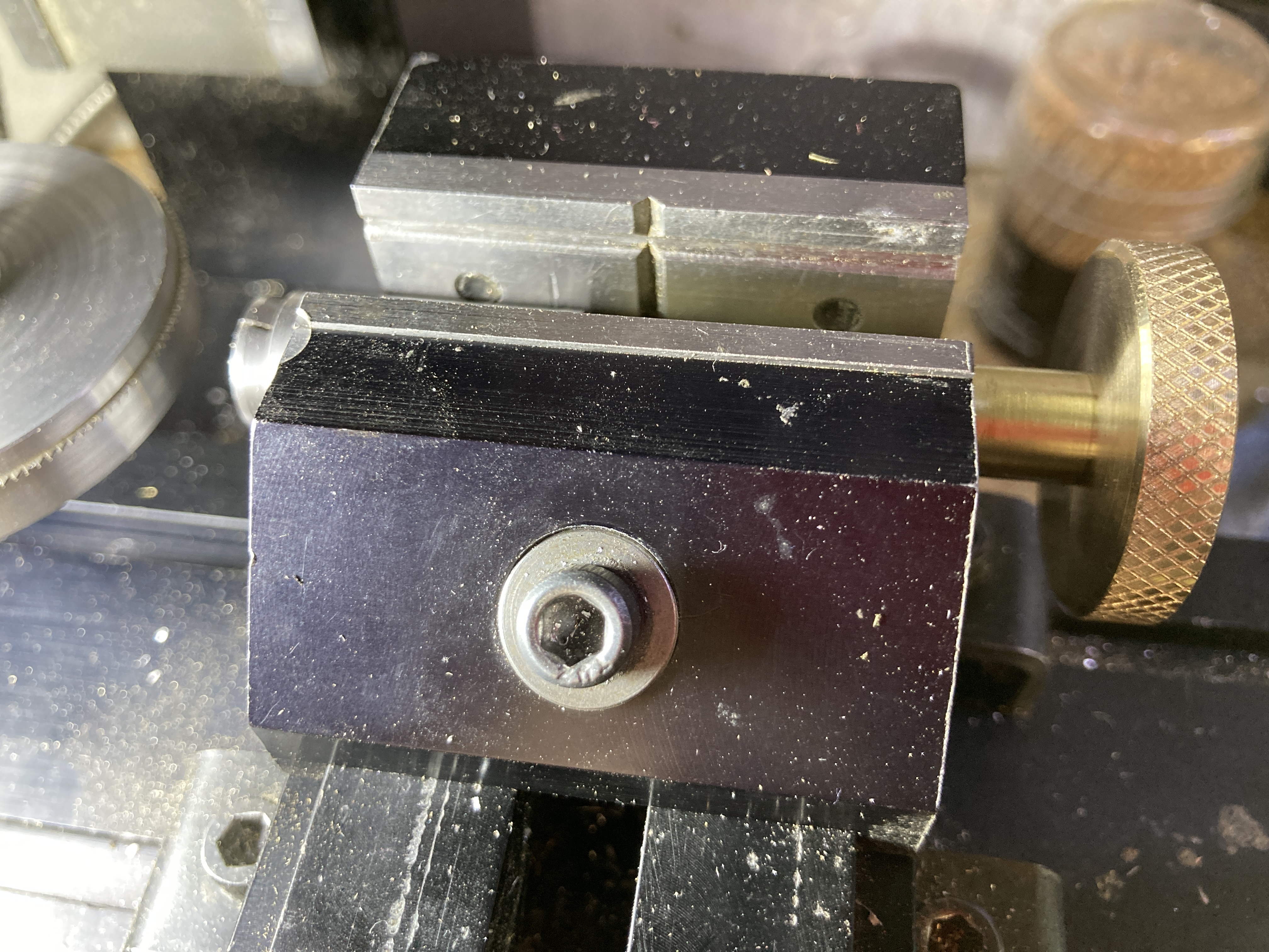
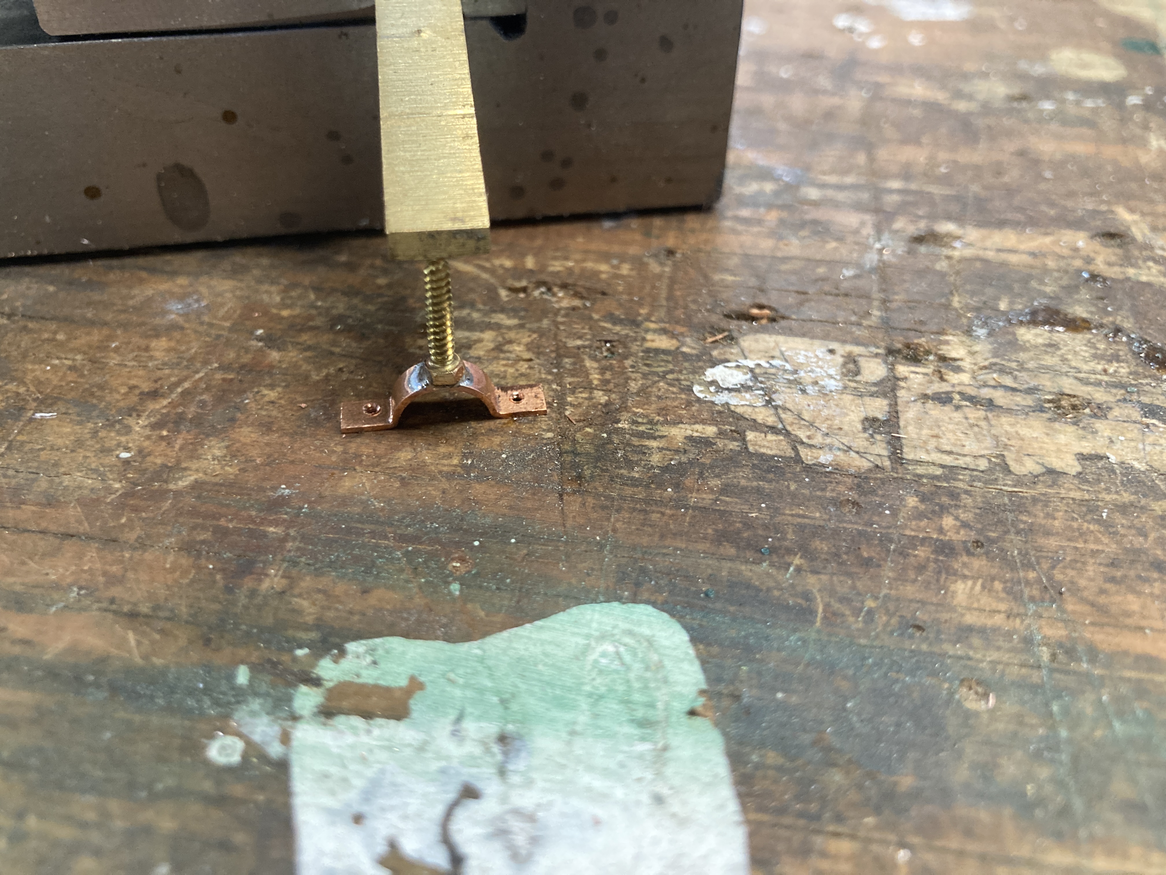
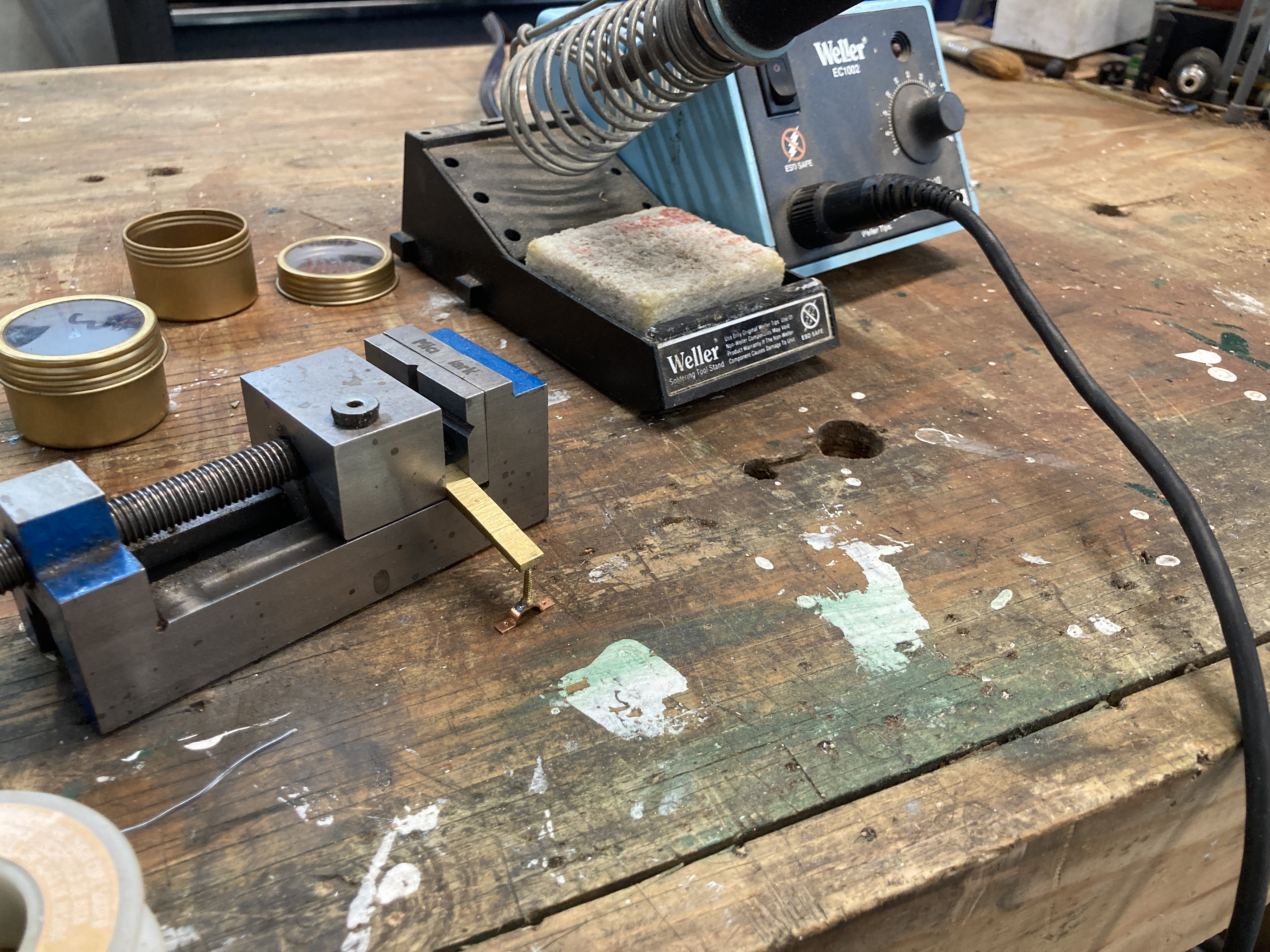
The last step in the fabrication of the brackets was to solder a wood screw to the back of the brackets. I turned down half of the hex head to form a round feature that fit in the center holes of the brackets.
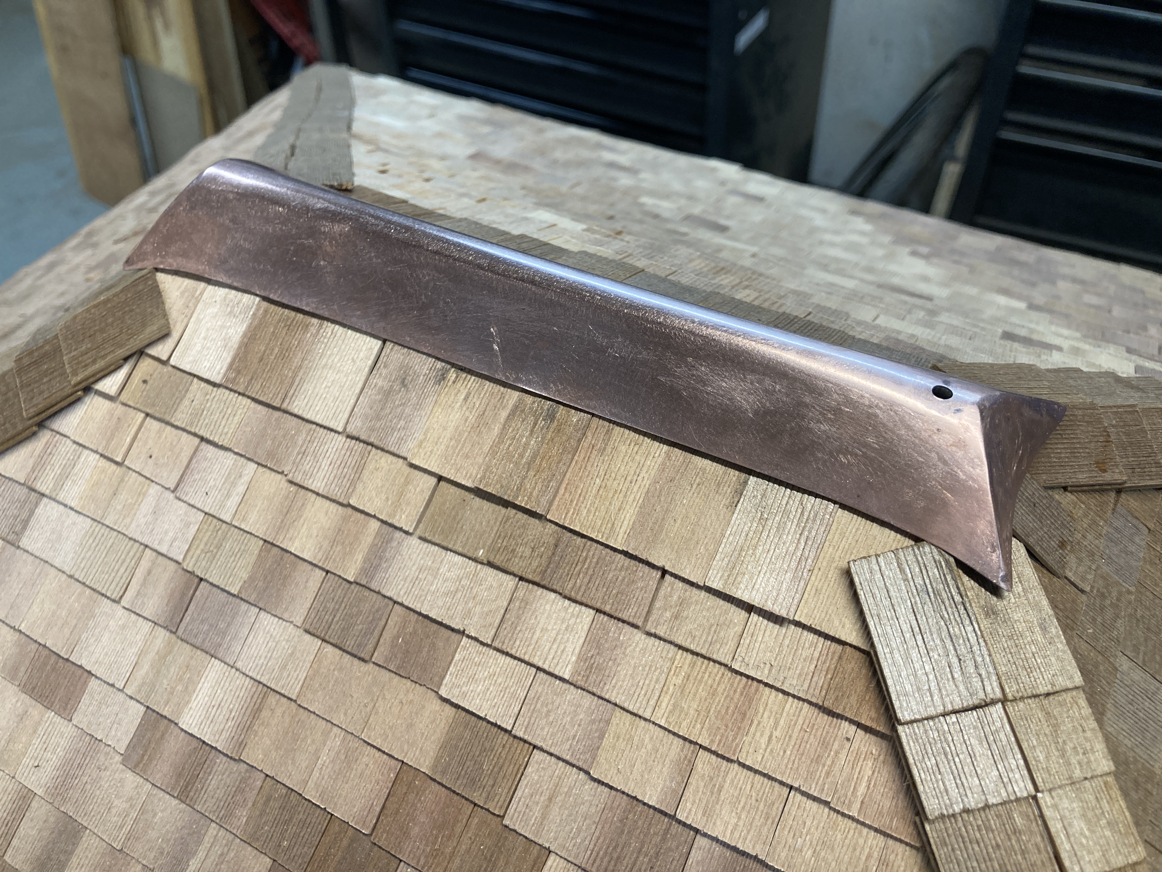
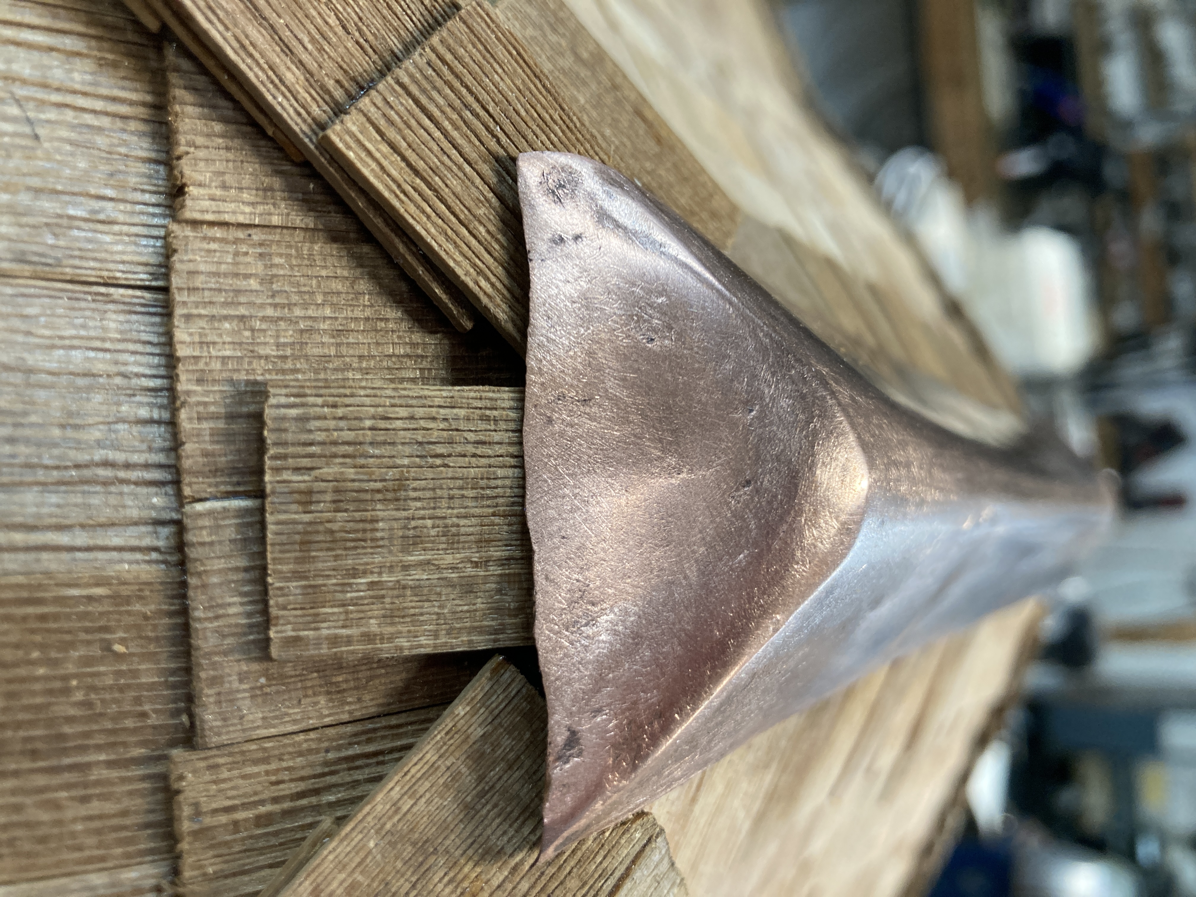
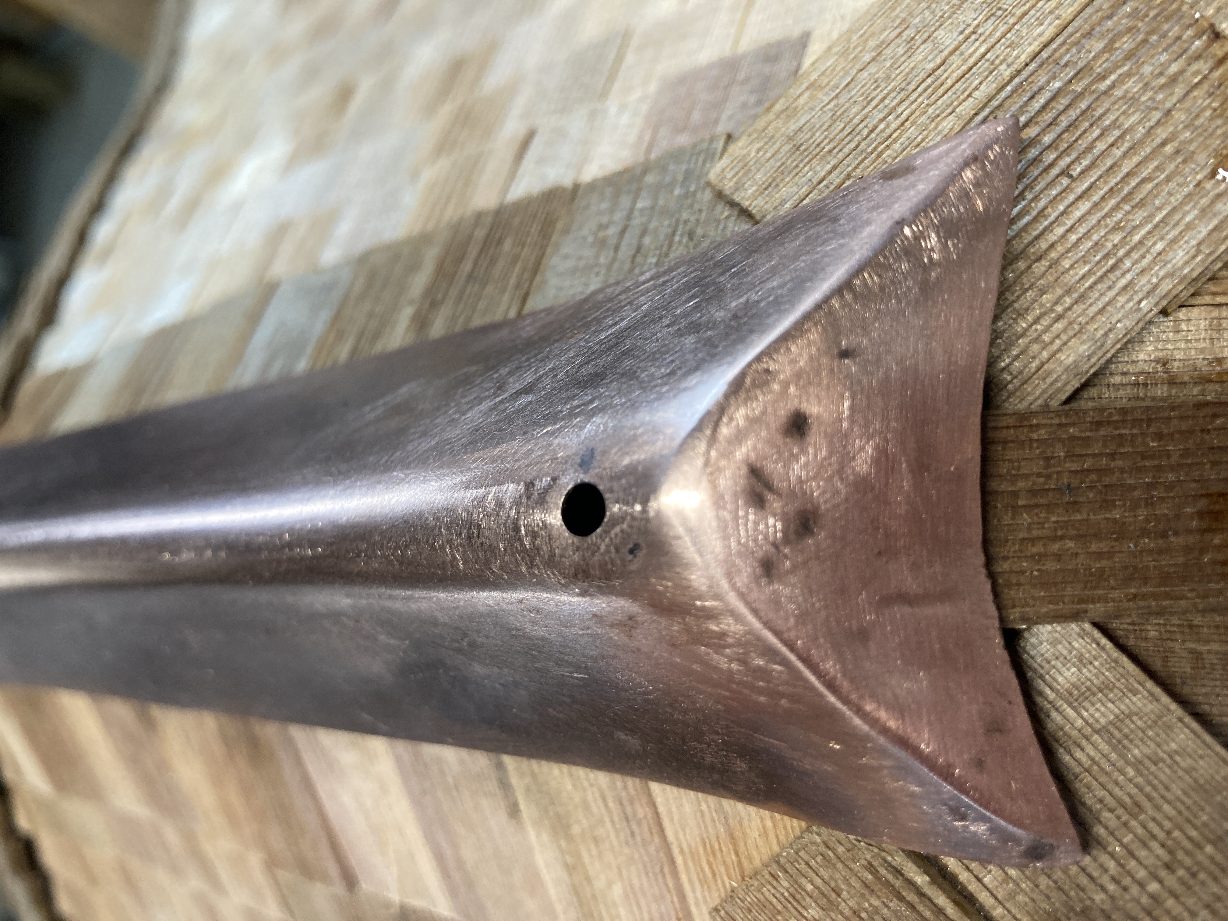
The next part was the roof top piece which on the original drawing was shown as being made of galvanised iron. I made mine from 0.5mm thick copper. I started by folding it lengthwise using the same press tool as I used to make the gutters but not pressing all the way. I then made a wooden buck to hammer form the ends. This involves many annealing cycles (heating the copper until it glows orange) and hammering. Copper work hardens so it becomes brittle if hammered too much in between each annealing. This was quite a tricky process and therefore I did not take any pictures duing the work.
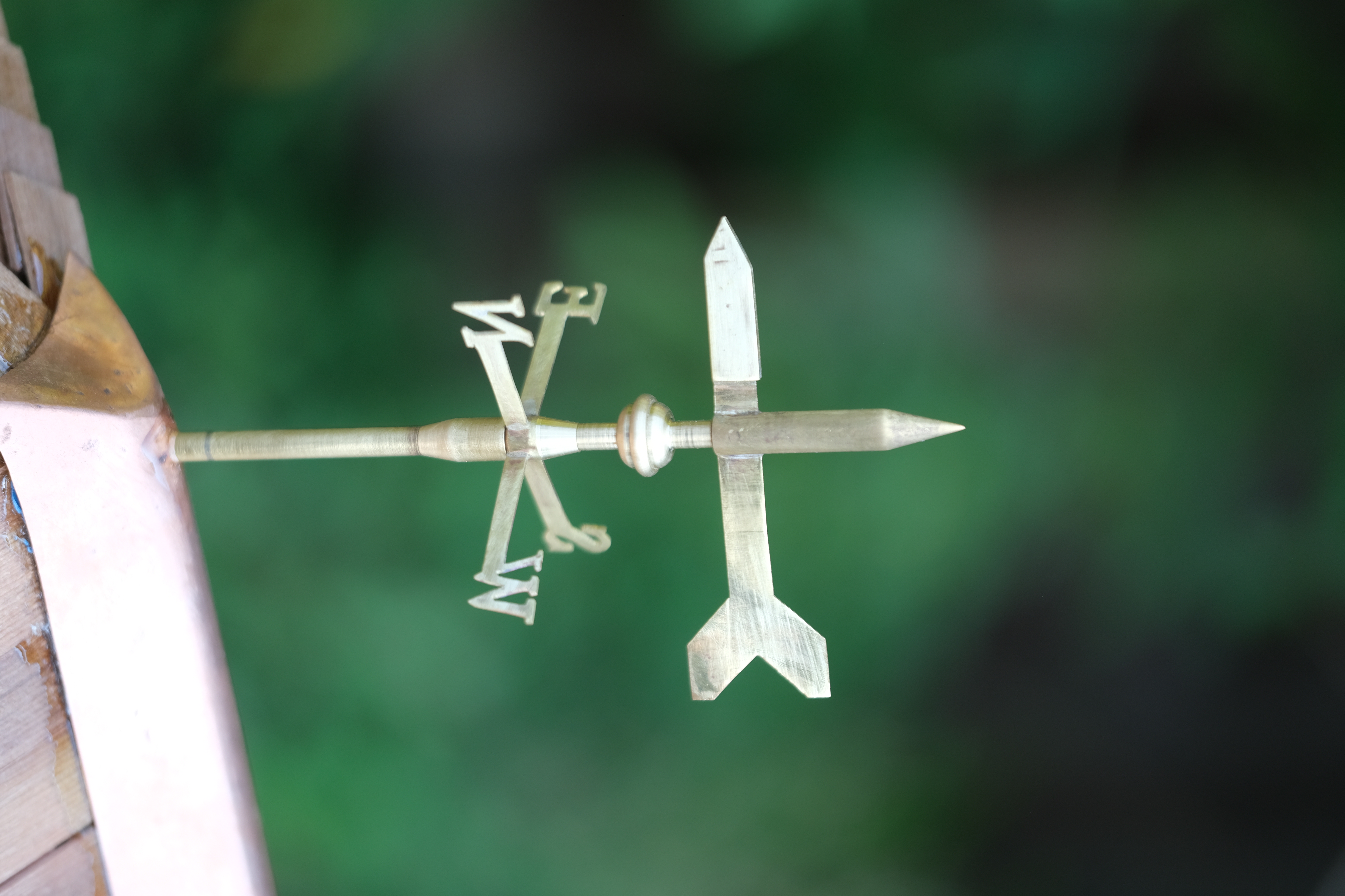
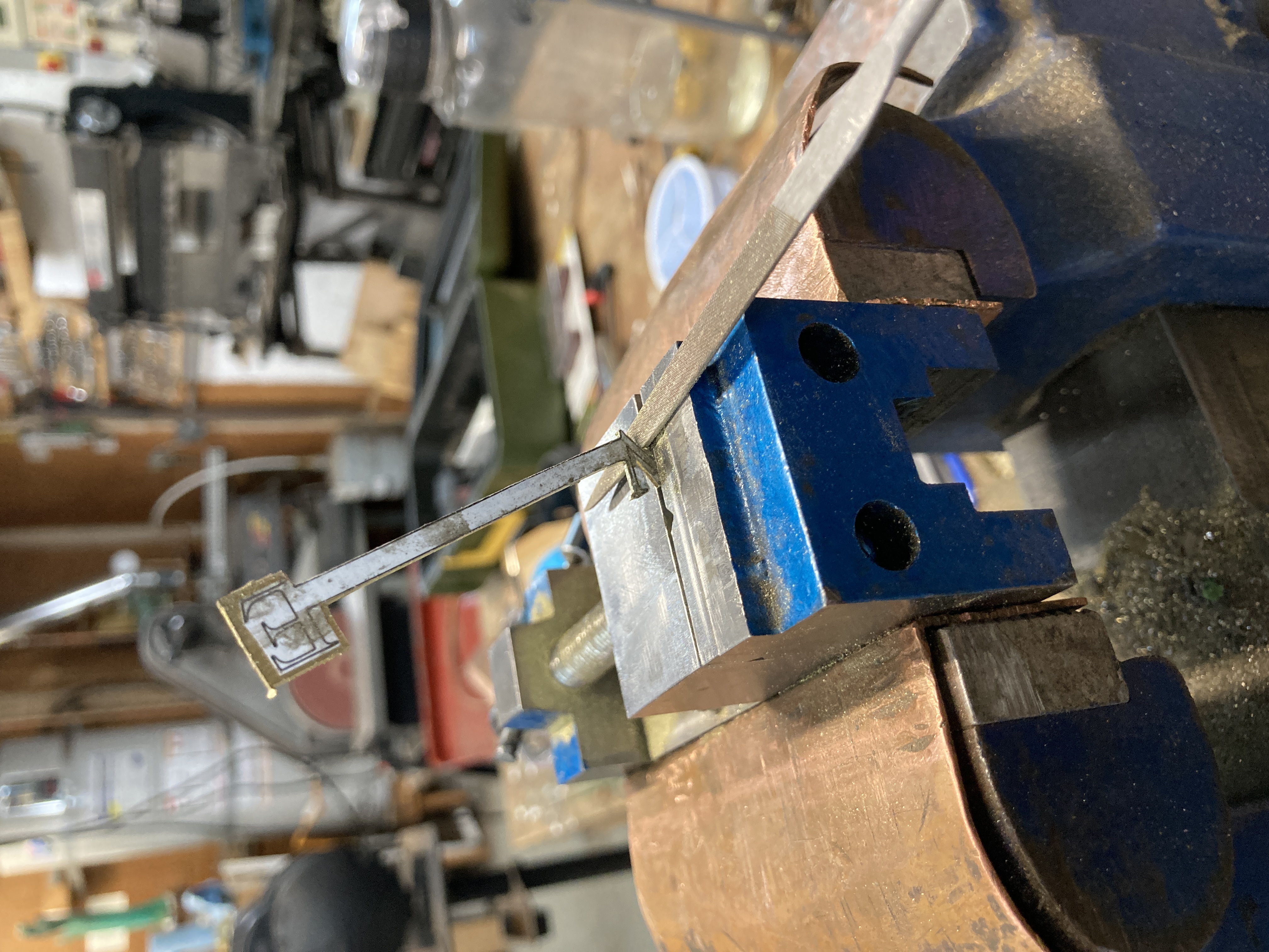
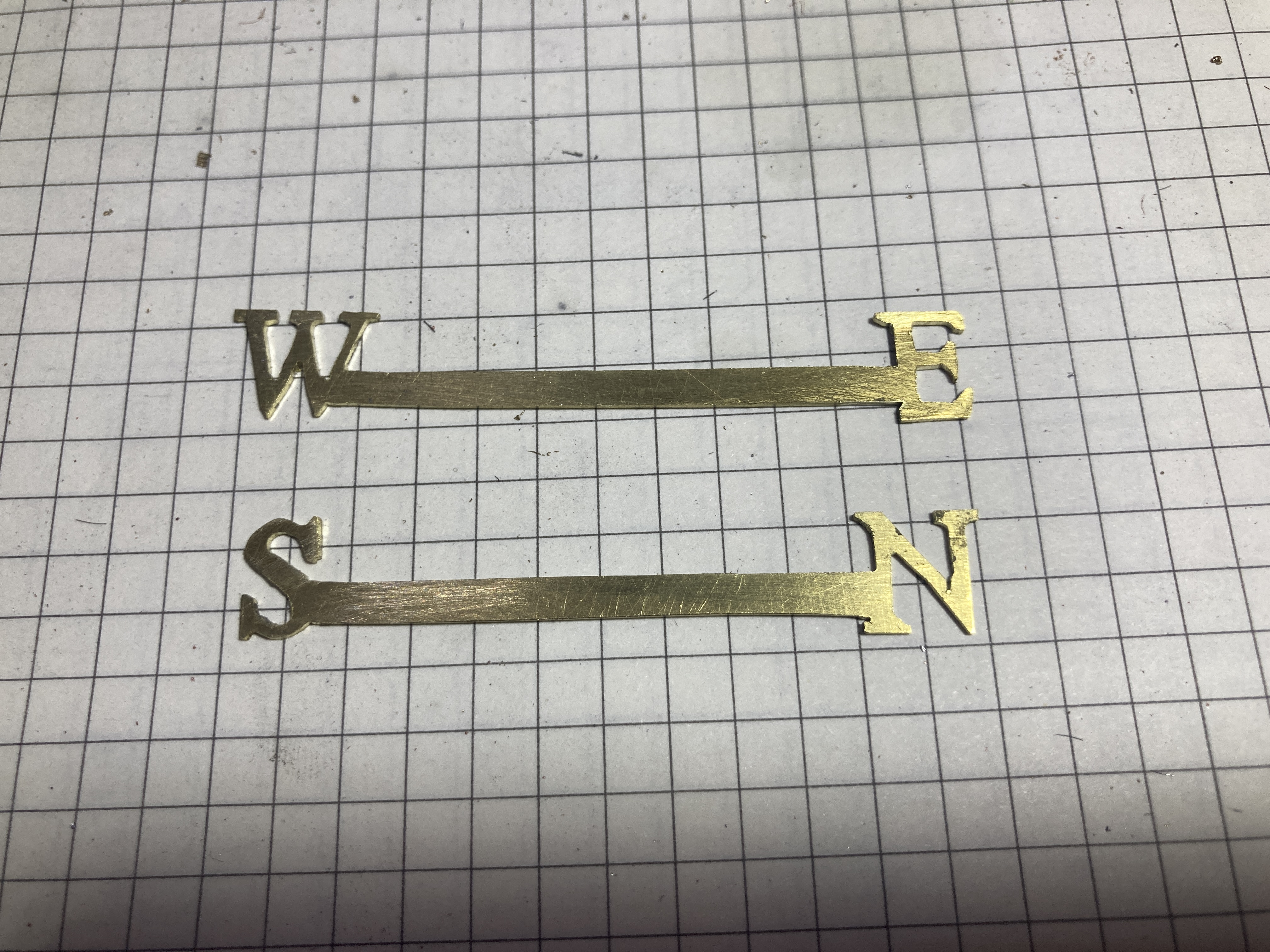
The very top of the building features a weather vane. I wanted mine to be to scale but alos functional. I also wanted to have a cardinal points indicator. To make the cardinal points, I drew them in CAD and printed the result full size. I then glued the paper to a 0.8mm sheet of brass. I then spent quite some time cutting them out with a variety of saws, files and sand paper.
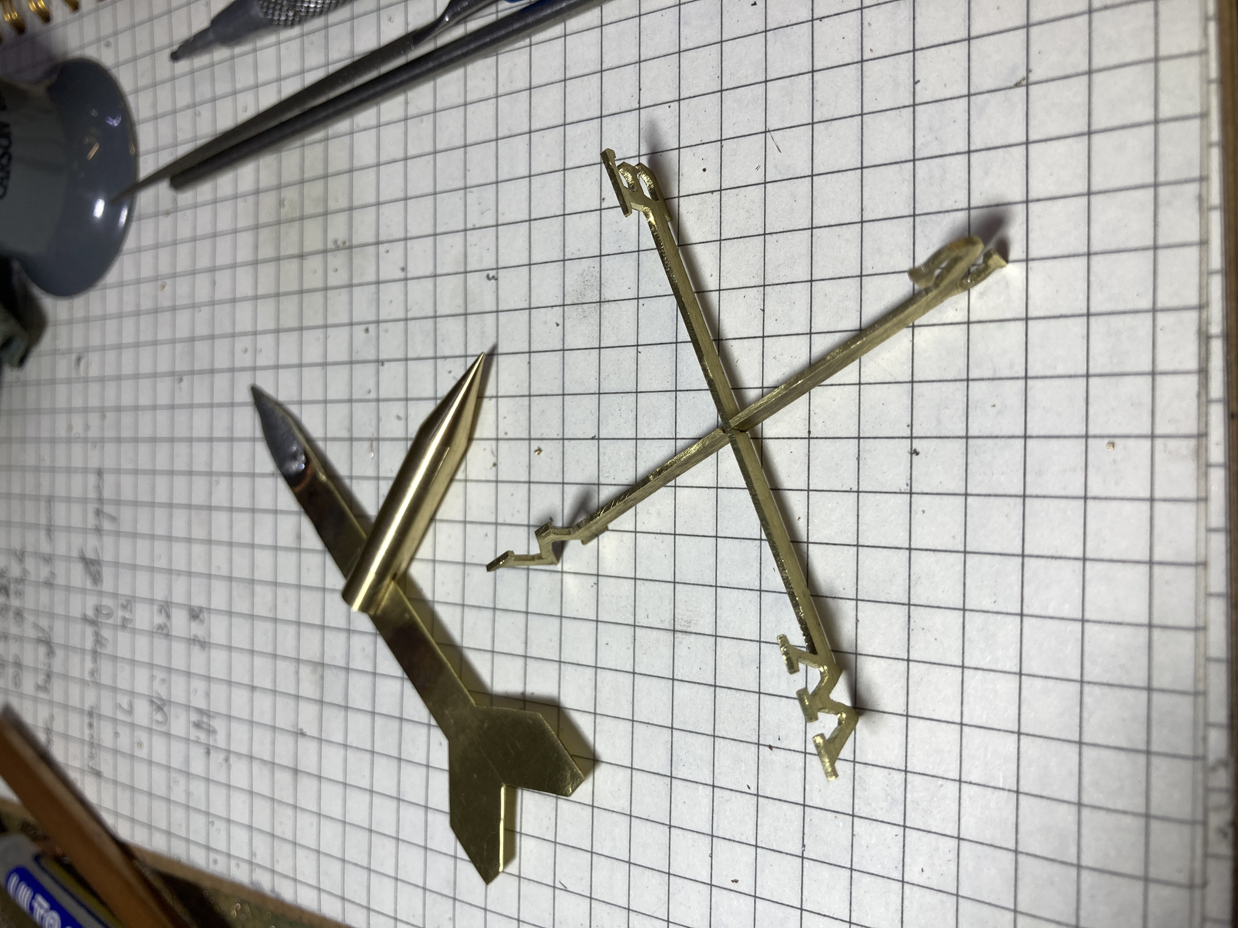
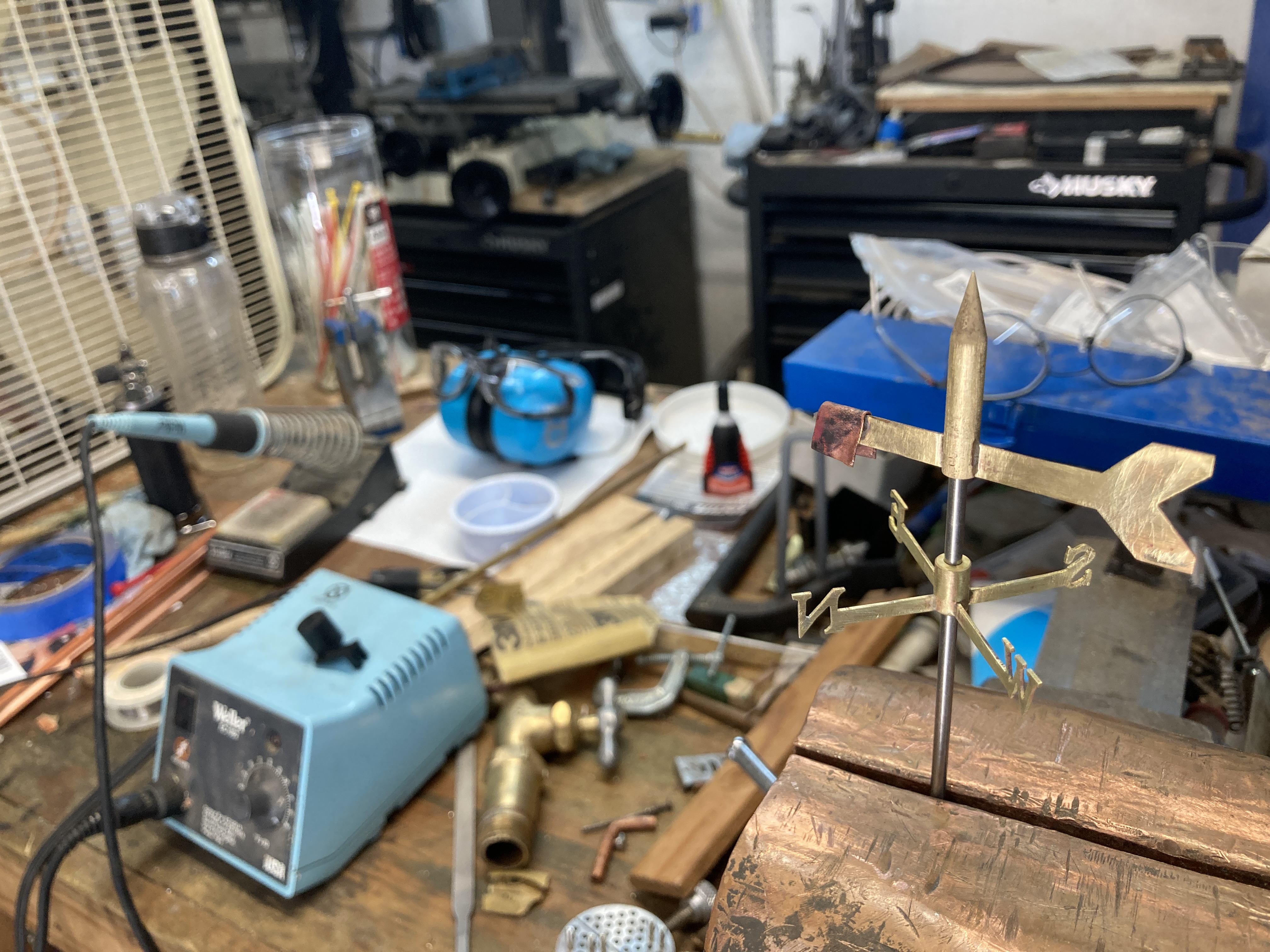
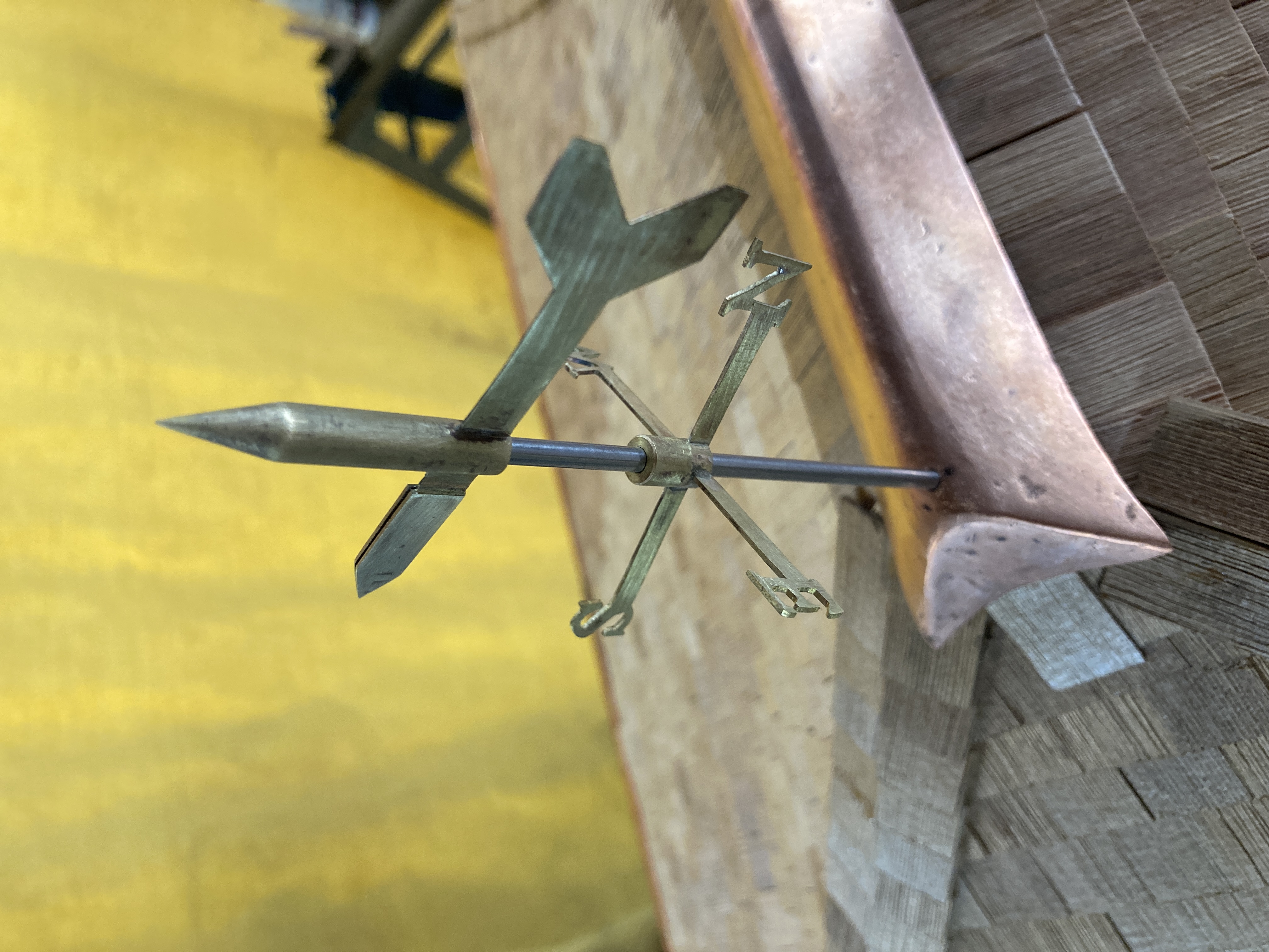
In order to create a free moving pivot point, I used a stainless steel center post with its upper end turned down to a point. The brass piece that supports the vane itself was drilled with a regular drill bit (3.5mm over the axle's 3.125mm diameter). This resulted in a point contact bearing. The vane was balanced, first with a bit of scrap copper and then by soldering extra layers of brass to the front of the arrow in order to balance out the extra mass of the back. This design results in a vane that points to the direction from which the wind is coming from.
One part not shown here is the painting: I used outdoor house paint for the wood and spray paint for the brass. The result is fine when viewed at a distance but is far from perfect upon close inspection!
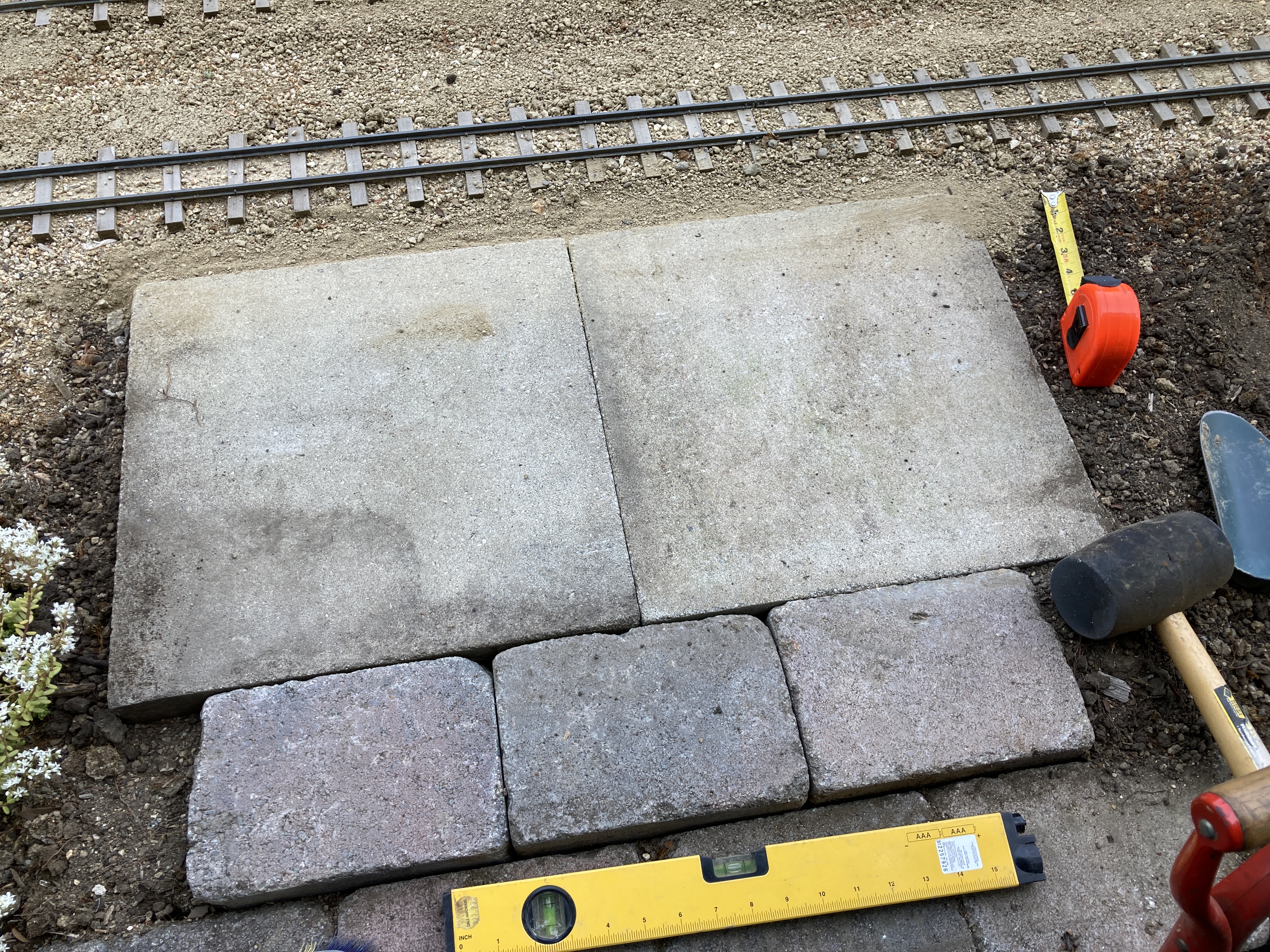
Moving outdoor, I created a foundation for the station by using some concrete pavers left over from other projects. I then moved the station using a cart as while it is not very heavy, it is quite bulky and the gutters are quite delicate!
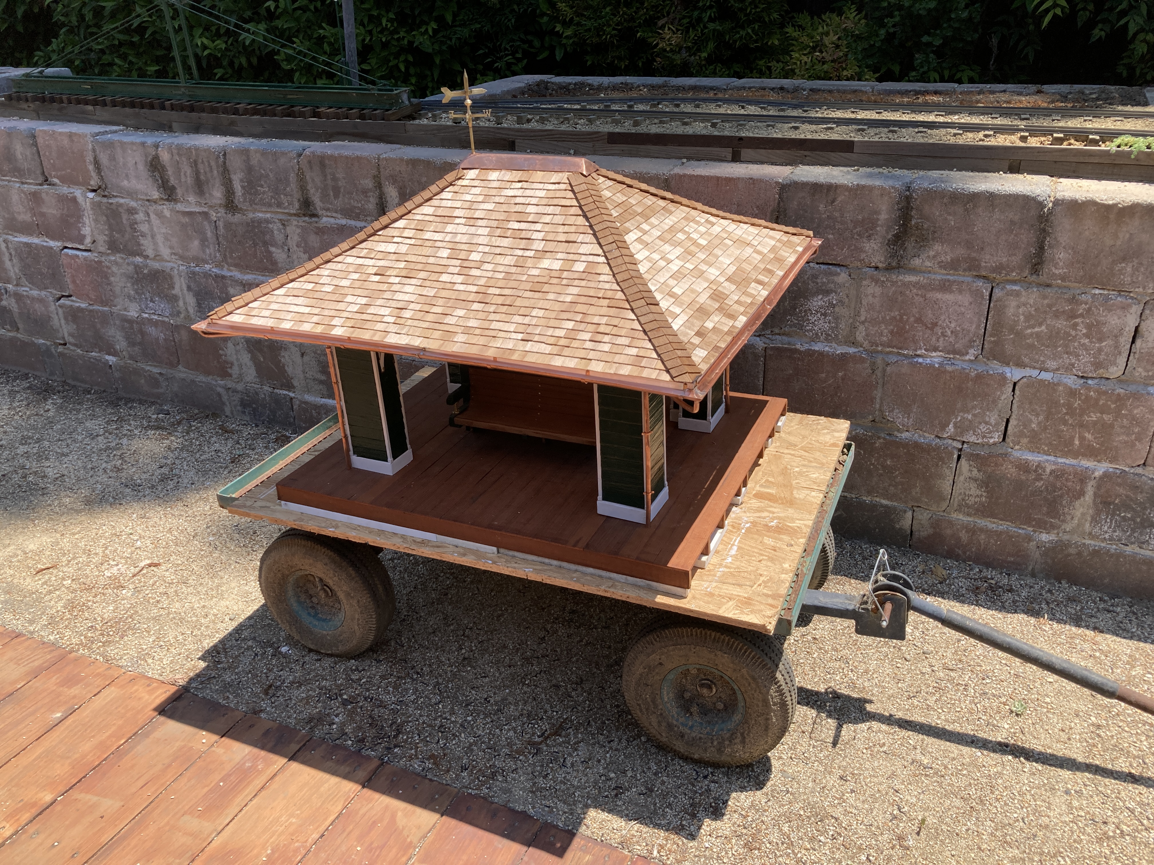
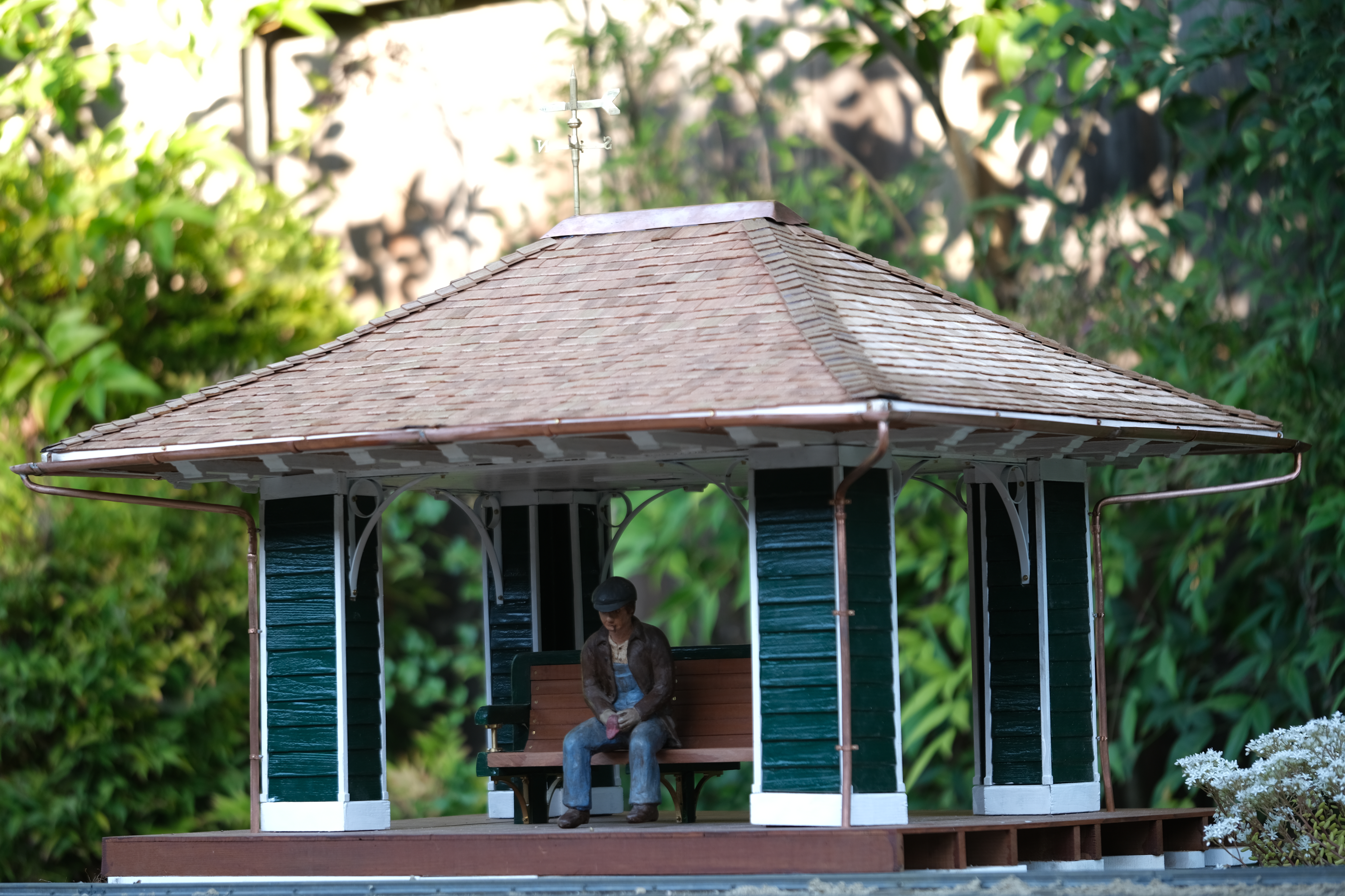
Here are a few more pictures of the finished station. Click on the thumbnails below to view the 26 megapixel originals.