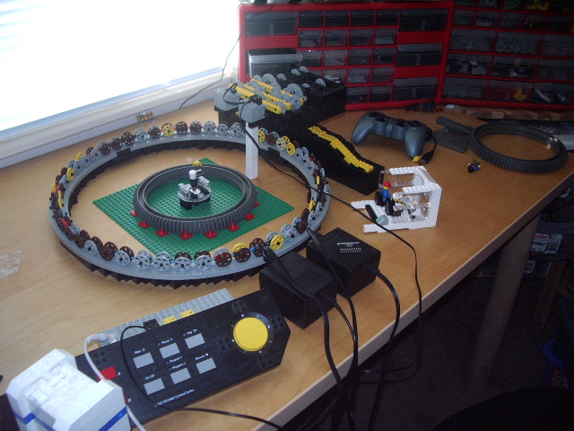


| The begining: the slewing ring (monorail track), one foot and its drive mechanism and the operator cab. |
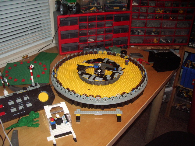
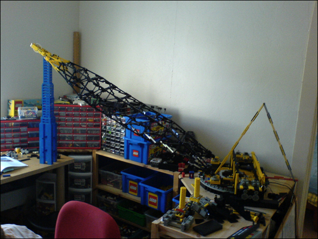
| Bir's eye view of the project as of 11-24-2005. |
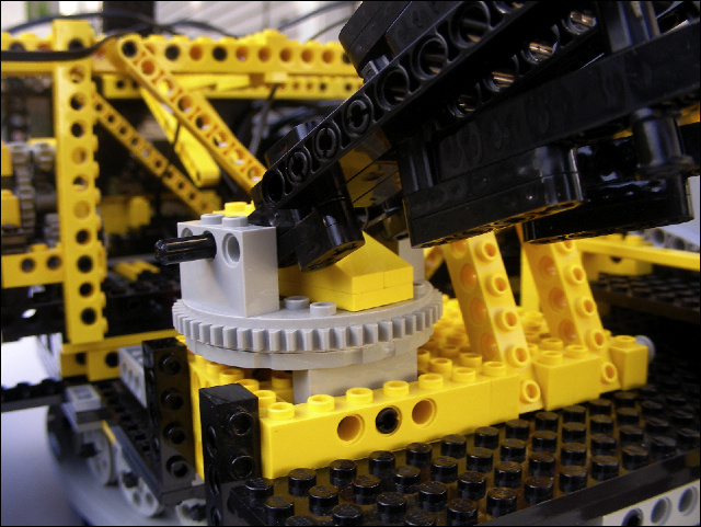
| This is the center turn table which includes a Mercotac rotary contact which will carry the power to the upper works. The slip ring is held in place by a slight press fit into a Lego clutch gear with its center hub removed. |
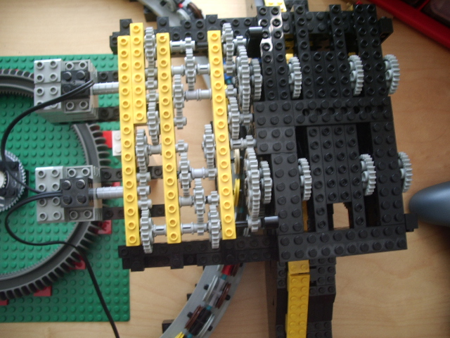
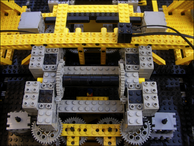
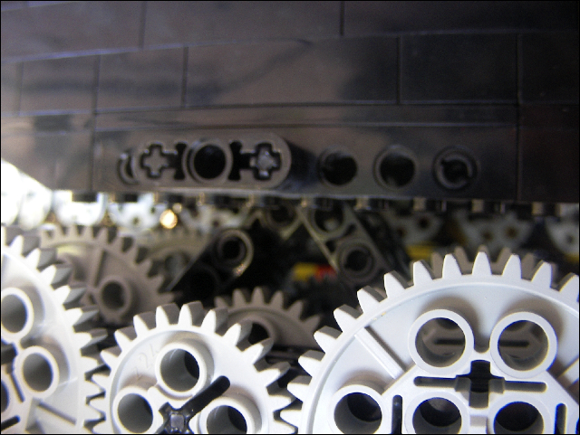
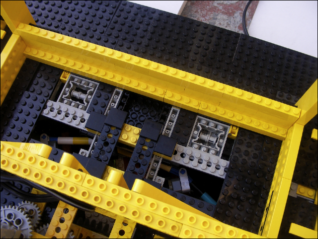
| Top view of the drive mechanism for one foot. |
| Here is the first foot, along with its drive mechanism. |
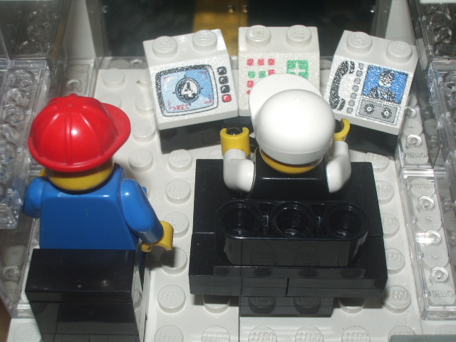
| Fron view of the operator cab. |
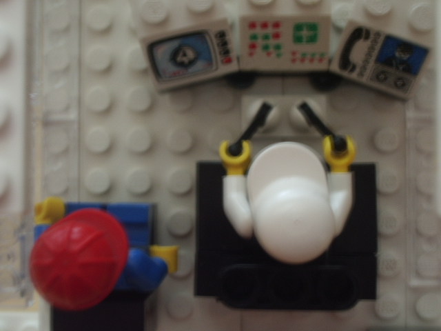
| Tope view of the cab showing the operator controls. Note that the oiler is learning on the job by observing the operator. This is how most operators learn their job. |
| IMGP1054.JPG |
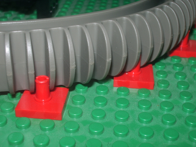
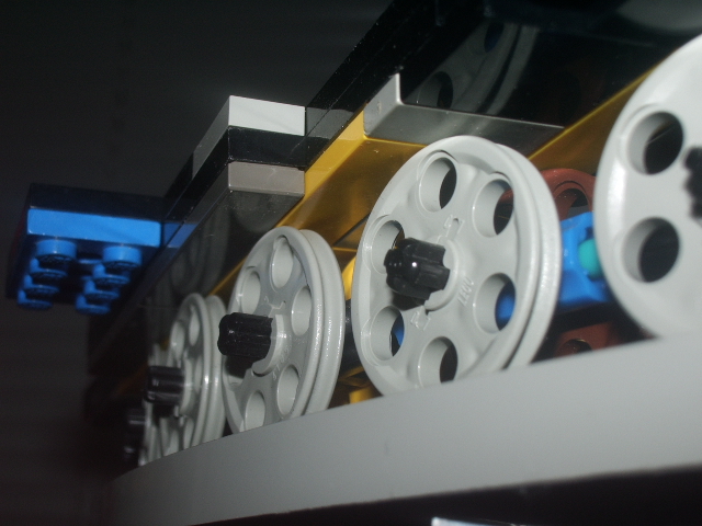
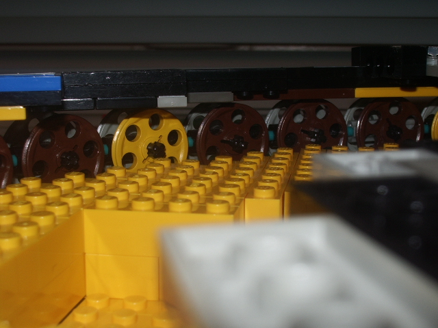
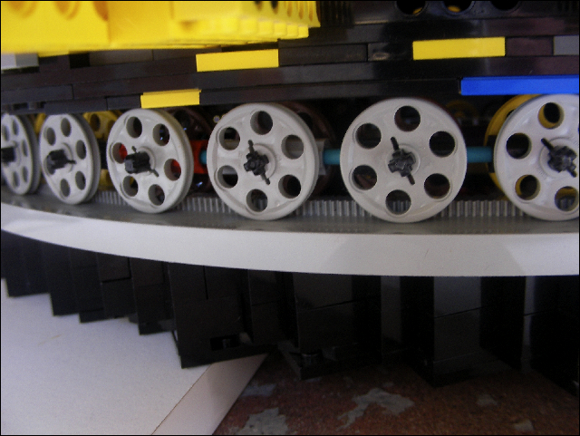
| These wheels are part of the slew ring main bearing. The grey part is a monorail track. |
| This show the begining of the tub (the circular base on which the crane rests). When complete, it will be at least four bricks high. |
| Closeup of the roller contruction for the main bearing. |
| Close up view of the intermediate slewing bearing. The green baseplate will be replaced by the tub as it is built. In addition to carrying part of the weight of the upper works, this ring's internal gearing will be used for powering the slewing function. |
| The tub has a bottom made of large plates flowwoed by three layers of bricks. |
| The mostly complete tub: I used yellow bricks for the inside because I have a lot of them! The outside "skin" is black... Also wisible on this picture is an excellent book: "Extreme mining machines, stripping shovels and walking draglines" by Keith Haddock, published by MBI, ISBN 0-7603-0918-3 |
| The top bearing surface for the intermediate bearing has been added. |
| The top bearing surface for the outer bearing has been added. |
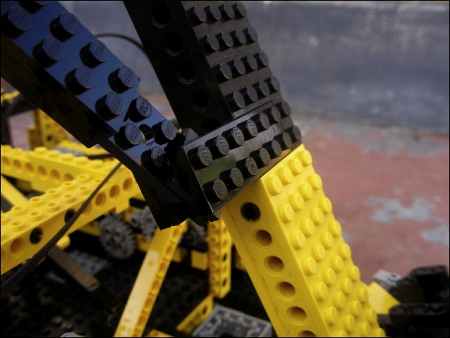
| This shot shows the foot setup next to the tub in order to get an idea of the final width... |
| Close up of the outer bearing showing the tiles mounted up side down to provide a smooth bearing surface. |
| Outer bearing viewed from the center of the machine. |
| This plate (along with three other) will connect the top bearing plate to the rest of the upper works. |
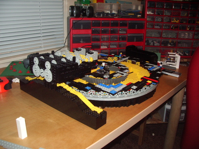
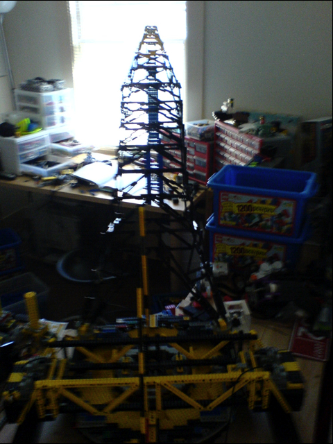
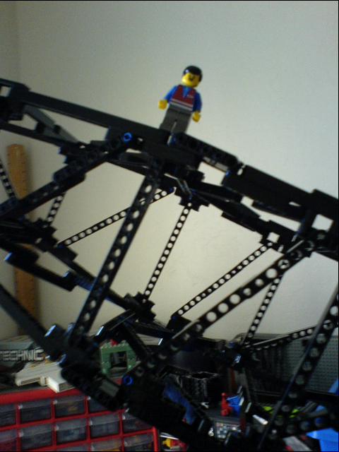
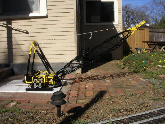
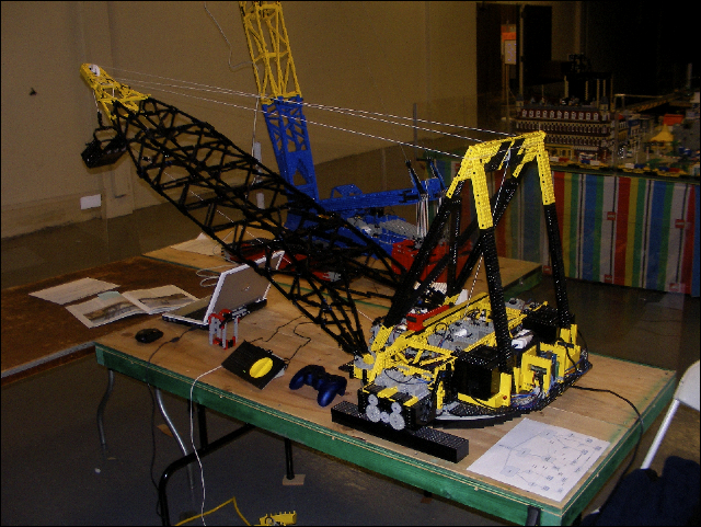
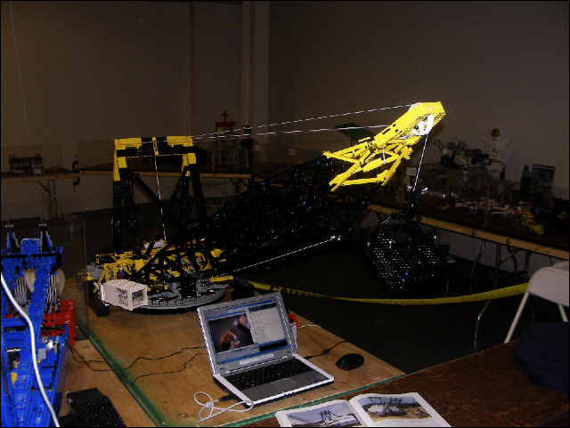
| The boom is now (June 2007) attached to the base. |
| DSC00774.jpg |
| DSC00775.jpg |
| DSC00777.jpg |
| DSC00778.jpg |
| DSC00776.jpg |
| DSC00779.jpg |
| DSC00773.jpg |
| SANY0001.jpg |
| SANY0002.jpg |
| SANY0003.jpg |
| SANY0004.jpg |
| SANY0005.jpg |
| SANY0006.jpg |
| SANY0012.jpg |
| SANY0013.jpg |
| SANY0014.jpg |
| SANY0015.jpg |
| SANY0016.jpg |
| SANY0017.jpg |
| SANY0018.jpg |
| SANY0019.jpg |
| SANY0020.jpg |
| SANY0021.jpg |
| SANY0022.jpg |
| SANY0023.jpg |
| SANY0025.jpg |
| SANY0028.jpg |
| SANY0030.jpg |
| SANY0031.jpg |
| SANY0032.jpg |
| SANY0033.jpg |
| SANY0034.jpg |
| SANY0035.jpg |
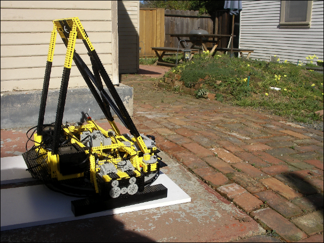
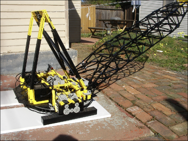
| Only two days after it was first completely assembled, I took it to Maker Faire for a two day display. It went very well. I ran it almost non stop for nearly 8 hours each day! |
| SANY0039.jpg |
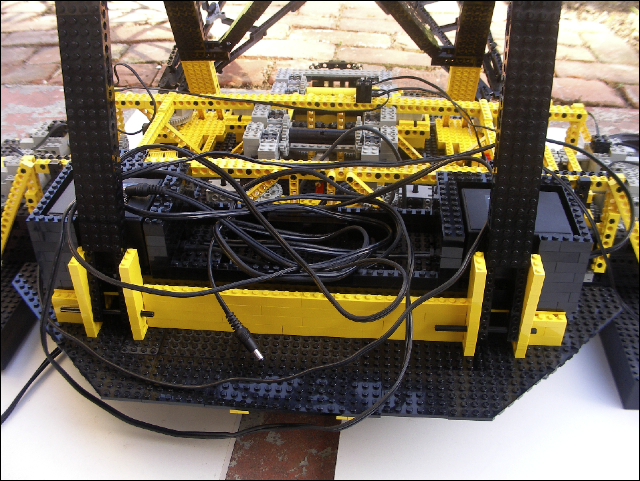
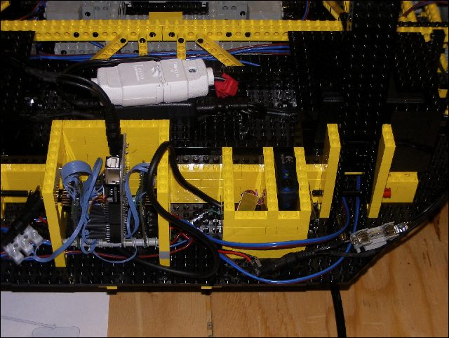
| Here is a view of the electronics. It needs to be tidied-up but it works very well... It is based around an Arduino board that emulates a Playstation game-port to talk to a Logitech wireless gamepad. |